MX3500N SIMULATION 7 – 99
<Set range and default value of each setup>
A to G:1step = 0.1mm
A. Document lead edge reference position: (L1), B. Paper lead
edge positions
Except for A and B, same as the item adjusted with SIM50-01.
The values adjusted with A and B are reflected to the document
lead edge reference position (RRC-A) and all the paper lead edge
positions (RRCB-**).
50-5
Purpose
Adjustment
Function (Purpose)
Used to set the lead edge adjustment value
which affects only the printer print.
Section
Printer
Item
Image quality
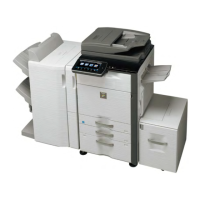
Operation/Procedure
1) Select the set item with [↑] and [↓] buttons.
The highlighted set value is switched and the value is dis-
played in the setting area.
* If there is any item over [↑], an active display is made and
item is shifted.
If there is no item over [↑], the display grays out and the
operation is invalid.
If there is any item under [↓], an active display is made and
item is shifted.
If there is no item over [↓], the display grays out and the
operation is invalid.
2) Enter the set value with 10-key.
* When [C] key is pressed, the entered value is cleared.
3) When [EXECUTE] button is pressed, it is highlighted and print-
ing for adjustment is started with the current set value.
After completion of printing, [EXECUTE] button returns to the
normal display.
* When [↑], [↓], [OK], [EXECUTE] button, [COLOR], or
[BLACK] key is pressed, the data are saved to EEPROM
and RAM.
* When [C], [CA], [SYSTEM SETTINGS], or [EXECUTE] but-
ton is pressed during printing, the operation is interrupted.
* When the machine returns to the ready state after occur-
rence of an interruption, self print is resumed.
4) Check the adjustment pattern image position.
Measure the dimensions of void area in the right and the left
frame direction of the adjustment pattern to check that the
dimensions are as follows:
If DEN-C = 3.0 ± 2.0mm and DEN-B = 3.0 ± 2.0mm, there is no
need to adjust.
If the values are as shown above, there is no need to adjust.
If not, go to step 5.
5) Change the adjustment values of A (DEN-C) and B (DEN-B).
When the adjustment value of A (DEN-A) is decreased by 1,
the sub scanning direction print start position is shifted toward
the paper lead edge by 0.1mm.
When the adjustment value of B (DEN-B) is decreased by 1,
the paper transport direction print range is extended toward
the rear edge by 0.1mm.
6) Repeat steps 1 to 5 until the conditions of step 4 are satisfied.
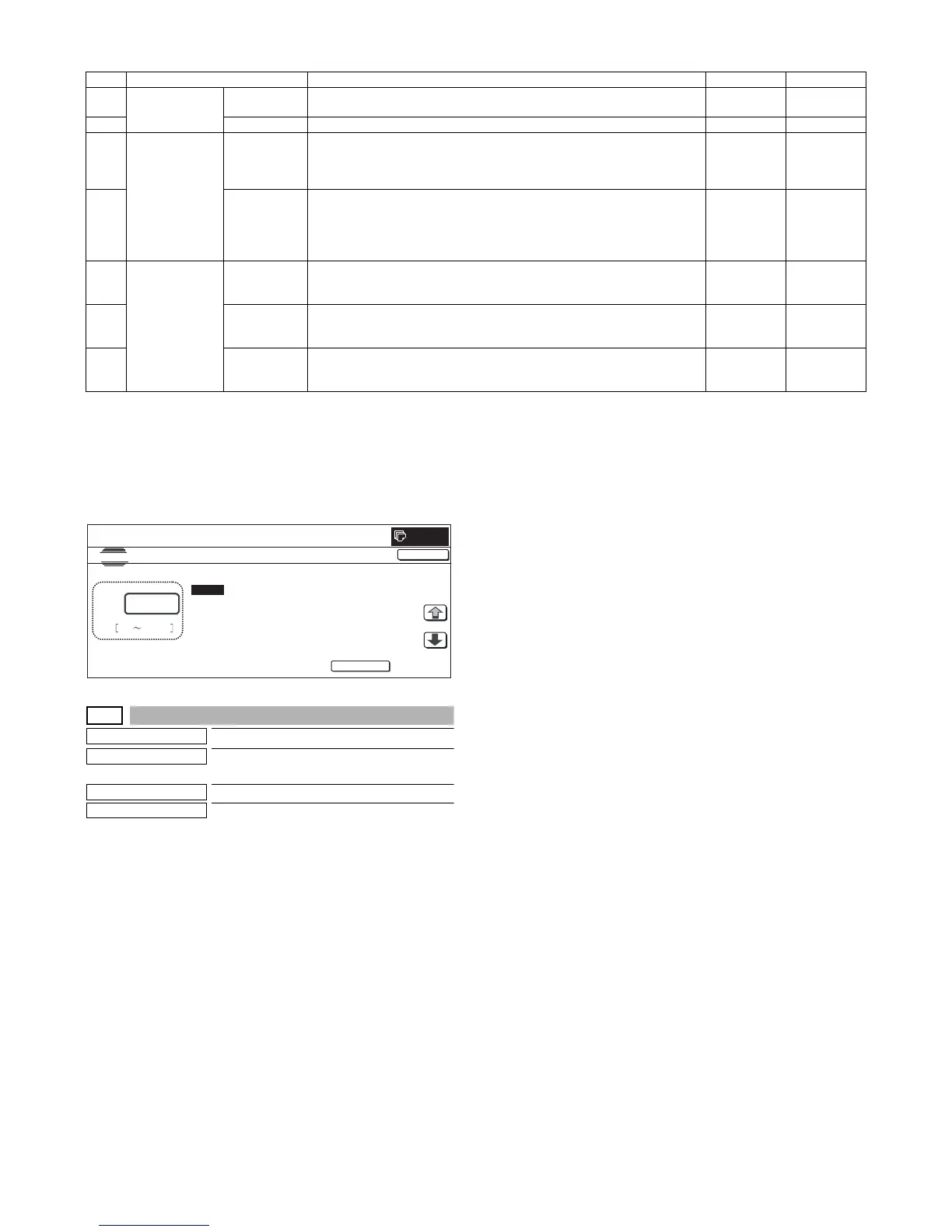
Item Display item Description Set range Default value
A Actual measured
value
L1 Distance between the image lead edge and the scale of 10mm (Platen 400%,
unit of 0.1mm)
0 to 999 –
B L2 Distance between the paper lead edge and the image lead edge (unit of 0.1mm) 0 to 999 –
C Image loss
quantity set value
LEAD Lead edge image loss quantity setting
The lead edge image loss quantity is specified. Difference between the
document lead edge scan start position and the document lead edge
* The greater the value is, the greater the image loss is.
0 to 99 30
D SIDE Side image loss quantity setting
The side image loss (SIDE) is specified. (Document width – Document edge
scan range / 2
(The rear edge image loss quantity is fixed to 0. (Without adjustment))
* The greater the value is, the greater the image loss is.
0 to 99 20
E Void quantity
setting
DENA Print lead edge adjustment
The void quantity at the paper lead edge is specified.
* The greater the value is, the greater the void is.
1 to 99 30
F DENB Sub scanning direction print range adjustment
The void quantity at the paper rear edge is specified.
* The greater the value is, the greater the void is.
1 to 99 20
G FRONT/REAR FRONT/REAR void quantity adjustment
The void quantities at the left and right edges of paper are specified.
* The greater the value is, the greater the void is.
1 to 99 20
CLOSE
0
A:
A㧦 60
B㧦 0
C㧦 30
D㧦 15
㧧
L1
㧧
L2
㧧
LEAD
㧧
SIDE
SIMULATION NO.50-02
LEAD EDGE ADJUSTMENT VALUE(CALC)
60
0 999
TEST
EXECUTE