MX3500N SIMULATION 7 – 102
50-10
Purpose
Adjustment
Function (Purpose)
Used to adjust the print off-center for each
tray.
Image print center position adjustment
(Adjusted for each paper feed section.)
Section
–
Item
Image quality (Image position)
Operation/Procedure
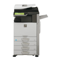
1) Select the set item with [↑] and [↓] buttons.
The highlighted section of the set value is switched and dis-
played on the set setting area.
* If there is any item over [↑], an active display is made and
item is shifted.
If there is no item over [↑], the display grays out and the
operation is invalid.
If there is any item under [↓], an active display is made and
item is shifted.
If there is no item over [↓], the display grays out and the
operation is invalid.
2) Enter the set value with 10-key.
* When [C] key is pressed, the entered value is cleared.
3) When [EXECUTE] button is pressed, it is highlighted and print-
ing for adjustment is started with the current set value.
After completion of printing, [EXECUTE] button returns to the
normal display.
* When [↑], [↓], [OK] button, [COLOR], or [BLACK] key is pressed,
the data are saved to EEPROM and RAM.
* When [C], [CA], [SYSTEM SETTINGS], or [EXECUTE] button is
pressed during printing, the operation is interrupted.
* When the machine returns to the ready state after occurrence of
an interruption, self printing is resumed.
<Description of item>
• Item A adjustment position
The main scanning direction paper size is greater than 216mm:
→ Reference: Main scanning direction print front image center
position (160mm from the BD sensor in the LSU unit) ±120mm in
the main scanning direction
The main scanning direction paper size is 257mm or less:
Reference: Main scanning direction print front image center posi-
tion (160mm from the BD sensor in the LSU unit) ±60mm in the
main scanning direction
• Adjustment direction
+ direction: Enlargement of magnification ratio
- direction: Reduction of magnification ratio
• When the adjustment value of item B to H is decreased by 1, the
main scanning print position is shifted to the front side by 0.1mm.
• When the adjustment value of item B to H is increased by 1, the
main scanning print position is shifted to the rear side by 0.1mm.
• Items J and K are displayed as "Display item: Detail of display."
Example: PAPER:CS1
Item Display item & Detail of display Item content Set range Default value Writing
A BK-MAG Main scan print magnification ratio BK 60 to 140 100 YES
B MFT Print off-center adjustment value (manual feed) 1 to 99 50 YES
C CS1 Print off-center adjustment value (Cassette 1) 1 to 99 50 YES
D CS2 Print off-center adjustment value (Cassette 2) 1 to 99 50 YES
E CS3 Print off-center adjustment value (Cassette 3) 1 to 99 50 YES
F CS4 Print off-center adjustment value (Cassette 4) 1 to 99 50 YES
G LCC Print off-center adjustment value (LCC) 1 to 99 50 YES
H ADU Print off-center adjustment value (ADU) 1 to 99 50 YES
I MULTI COUNT Print quantity 1 to 999 1 NO
J PAPER MFT Cassette select Manual feed 1 to 6 1 2 (CS1) NO
CS1 Cassette 1 2
CS2 Cassette 2 3
CS3 Cassette 3 4
CS4 Cassette 4 5
LCC LCC 6
K DUPLEX YES Duplex print select Selected 0 to 1 0 1 (NO) NO
NO Not selected 1
0