MX3500N FUSING SECTION N – 9
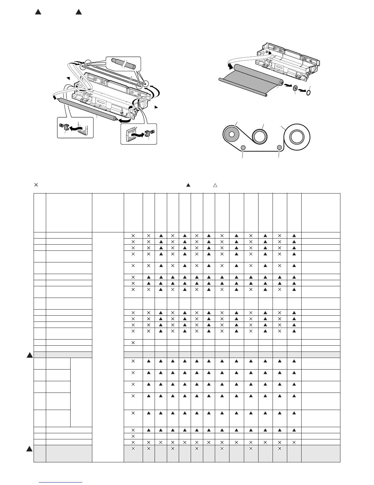
4) Remove the web spring and the pressure roller bearing (A).
Remove the pressure roller (B). Remove the web tension shaft
(C).
* When installing, arrange so that the one-notch side (D) of
the upper web roller is on the front side.
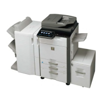
5) Remove the upper web roller (A). Remove the web brake col-
lar (B), and the web break rubber (C) from the upper web
roller.
* When installing, place the upper web roller (C) between the
pressure roller (A) and the web shaft (B) as shown below.
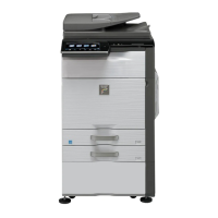
4. Maintenance
: Check (Clean, replace, or adjust according to necessity.) {: Clean : Replace : Adjust ✩: Lubricate : Shift the position.
F
R
A
A
B
C
A
B
C
A
B
B
C
C
No. Part name
Monochrome
supply/
Mechanical
parts
When
calling
150
K
300
K
450
K
600
K
750
K
900
K
1050
K
1200
K
1350
K
1500
K
1650
K
1800
K
Remark/Refer to
the Parts Guide.
Block/Item No.
(Only the
replacement
parts are
described.)
1 Upper heat roller Mechanical
parts
(P/G No.: [31]-42)
2 Lower heat roller (P/G No.: [32]-13)
3 Fusing gear (P/G No.: [31]-40)
4 Upper heat roller
bearing
(P/G No.: [31]-41)
5 Lower heat roller
bearing
(P/G No.: [32]-11)
6 Sub roller
7 Sub roller bearing
8 Upper separation
pawl
(P/G No.: [33]-23)
9 Lower separation
pawl (Japan only)
(P/G No.: [32]-43)
10 Upper thermistor side (P/G No.: [31]-24)
11 Upper thermistor sub (P/G No.: [31]-24)
12 Lower thermistor (P/G No.: [32]-37)
13 Upper thermistor C
(Non-contact)
(P/G No.: [31]-15)
14 Gears ✩✩✩✩✩✩✩✩✩✩✩✩Specified position
15 Paper guides { {{{{{{ { { { { { {
17 Upper
Web roller
Supplied
by Web
unit
18 Pressure
roller
19 Web roller
bearings
20 Pressure
roller
bearing
21 Web
break
rubber
22 Web unit
23 Transport rollers {{{{{{ { { { { { {
24 Discharge brush
25 Heat rollers ✩ ✩ ✩ ✩ ✩ ✩ Grease (JFE552)
(UKOG-
0235FCZZ)
5
6
: Jul. 15 2006, : Oct. 15 2006
5
6