Internal
VOC1
configuration
•
Clock
inputs
\;jfOneof
the three clocks,
CKO,
CK1,
and
CK2,
is
selected
01
[With the
DO
and
01
on
the
I/O
port,
and
is
halved.
tlbf
O
!;/
RESET
Fig.
75
• Dot clock and 2xCCLK
outputs
D2
r-
_____
2GCK
GCK
t-T---+2XCCLK
1-----4RAs
"dOt"C'KLOAD
Fig. 76
The
2xCCLK
is
obtained from dividing
the
ESCK by 8.
The
dot
clock
is
switched by
the
I/O
port
02,
for
the
320
dot mode.
{ *
RASand CAS
•
, ,
;
ESCK
GCK
CAS
'---------+CRL
S/L
RCS
RS
F/F
Fig. 77
The
RAS
and CAS signals are created from
the
2xCCLK,
by
delaying it and
then
gating it.
In
the
320
dot
mode,
the
Shift/load (S/Ll
is
added each time.
*
ERAS:
RASO-5
are created from ERAS.
*
EVDE:
VDEO-2 are created from EVDE.
* RASMASK, CASMASK: Prevents RAS
and
CAS
from being set high while
the
GDC
is
* REF:
drawing.
Prevents
CAS from becoming active
during
VRAM refresh.
AI7
AI6
-
MZ-5600
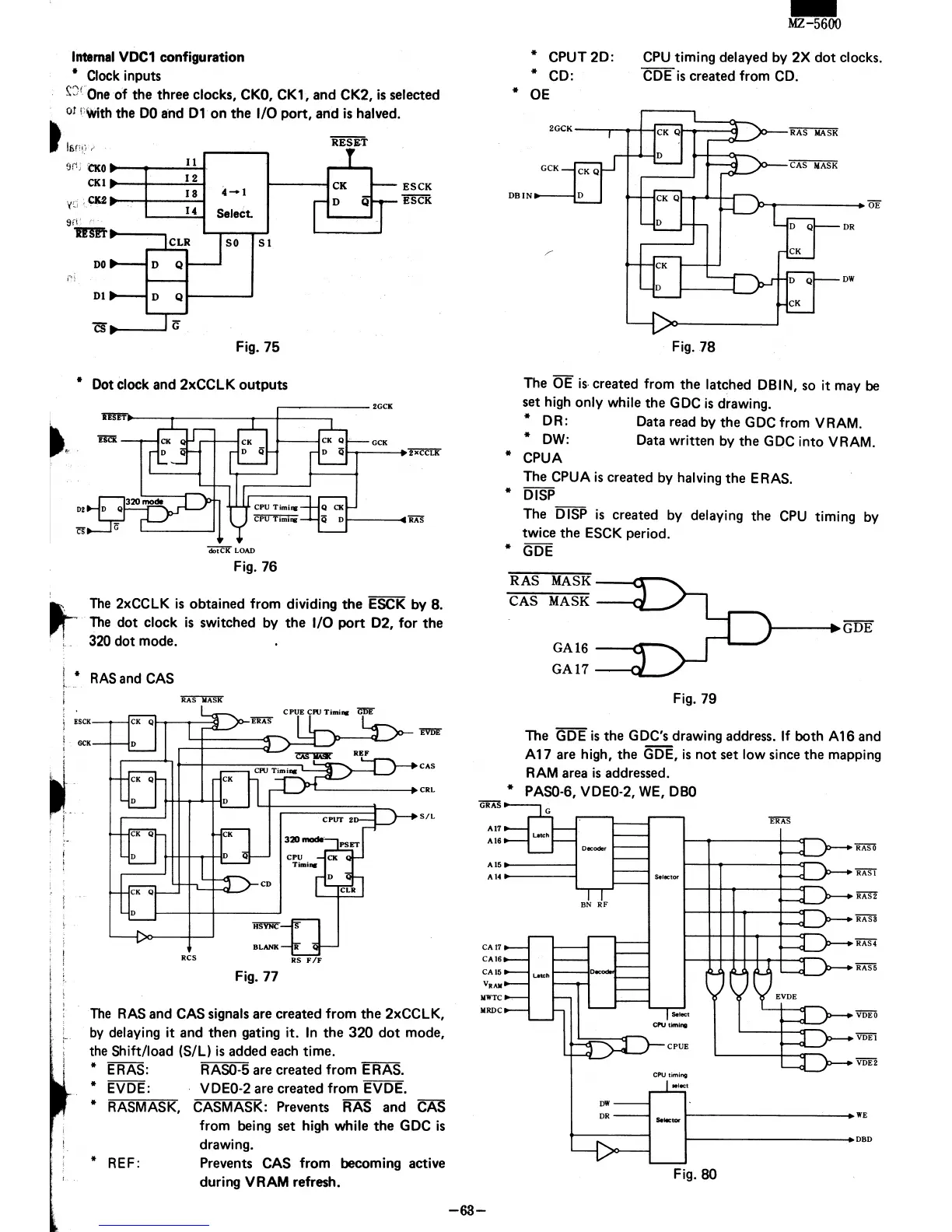
*
CPUT2D:
* CD:
CPU
timing delayed by 2X
dot
clocks.
CDE
is
created from CD.
* OE
P-t------+
TIE
DR
DW
Fig.
78
The OE
is,
created from
the
latched DBIN, so it may be
set high only while
the
GDC
is
drawing.
* DR: Data read by
the
GDC from VRAM.
*
DW:
Data written by
the
GDC into VRAM.
* CPUA
The CPUA
is
created by halving
the
ERAS.
* DISP
The DISP
is
created by delaying the
CPU
timing by
twice the
ESCK period.
* GDE
RAS
MASK
----c:::r-___......
CAS
MASK
---<~
GA 16
-----i~___......
GA17
--(y
Fig. 79
t---~GDE
The GDE
is
the GDC's drawing address.
If
both A
16
and
A 17 are high,
the
GDE,
is
not
set
low since
the
mapping
RAM
area
is
addressed.
* PASO-6, VDEO-2,
WE,
DBO
Decoder
AI5_----j
AI4_----I
Selector
CA17
CAt6
CA15
V.AM
I/WTC
I/RDC
-63-
BN
RF
DW
OR
CPU
timing
.'eet
Se,.,
...
t----------_WE
t----------_OBO
Fig.
80