(9)
Display signal
output
logic
,-~~----~~---------------+OHSYNC
--~~----~-+--~-----------+OVSYNC
~--~------+--+~~~---------+OR
~-+~~---+~r-+--r~-------;~G·
,-----
10
~GND
~~-+--~+--+----+ODOTCLK
~+-;--+-;----~~
~+-;--r--~O~
~+--+--~~R
~+---;OG
L----+Oii
l
___
_
r,::-
---
1
0
i!I-fOGND
~--------------------~IK)v[DEO
Fig. 100
10
10
L..:
___
_
•
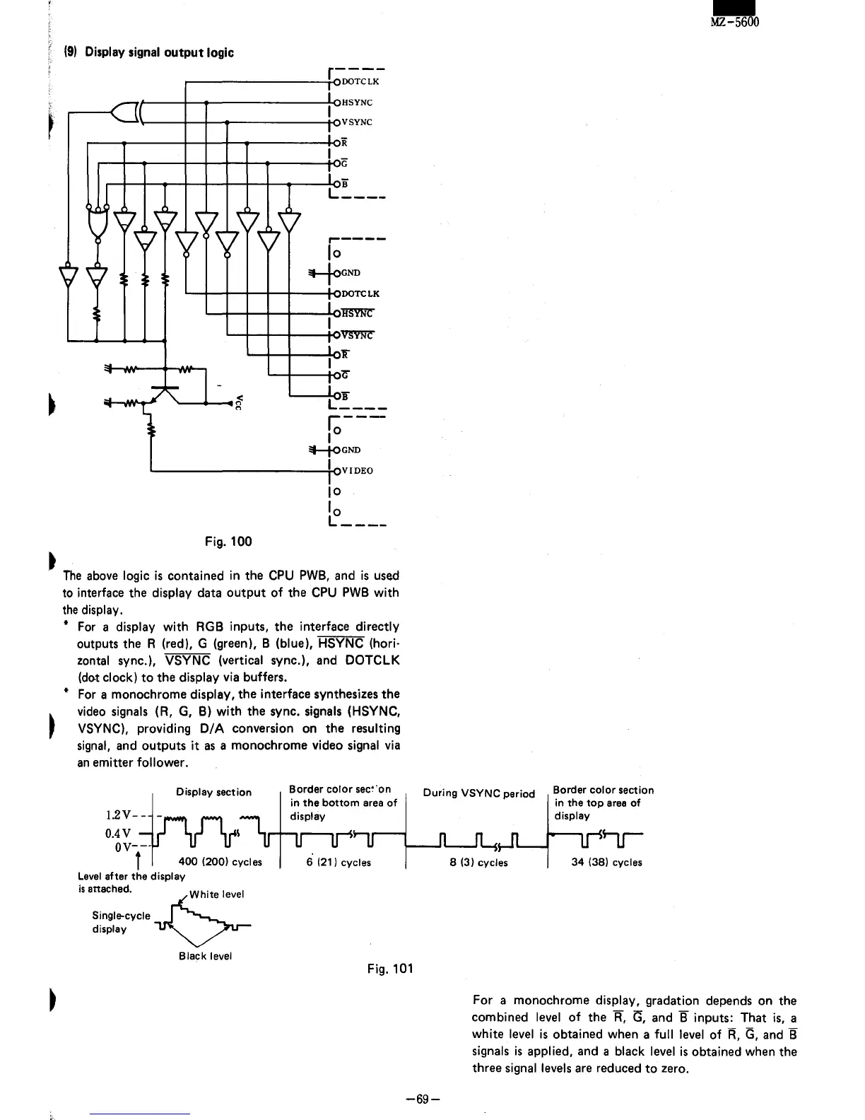
The
above
logic
is
contained in the
CPU
PWB,
and
is
used
to interface the display data
output
of
the
CPU
PWB
with
the
display.
*
For
a display
with
RGB inputs, the interface directly
outputs the R (red), G (green), B (blue), HSYNC (hori'
zontal sync.), VSYNC (vertical sync.), and
DOTCLK
(dot clock)
to
the display via buffers.
*
For
a monochrome display, the interface synthesizes the
video
signals
(R,
G,
B)
with
the sync. signals (HSYNC,
VSYNC),
providing
Of
A conversion on the resulting
signal,
and outputs
it
as
a monochrome video signal
via
an
emitter follower.
1.2
V
_§._
Display section
D.4V
\
DV-f-
400
(200) cycles
Level
after
the
display
is
attached.
White
level
Single-cycle
~
.~.~.
display
~
Black level
Border
color
sec~·on
in
the
bottom
area
of
display
6 (21) cycles
During
VSYNC
period
8 (3) cycles
Border
color
section
in the
top
area
of
display
34
(38) cycles
-
MZ-5600
Fig.
101
-69-
For a monochrome display, gradation depends on the
combined
level
of
the
R,
<3,
and B inputs: That
is,
a
white
level
is
obtained when a
full
level
of
R,
G,
and
B
signals
is
applied, and a black level
is
obtained when the
three
signal levels
are
reduced
to
zero.