4.3.2 Signal system of the 8253
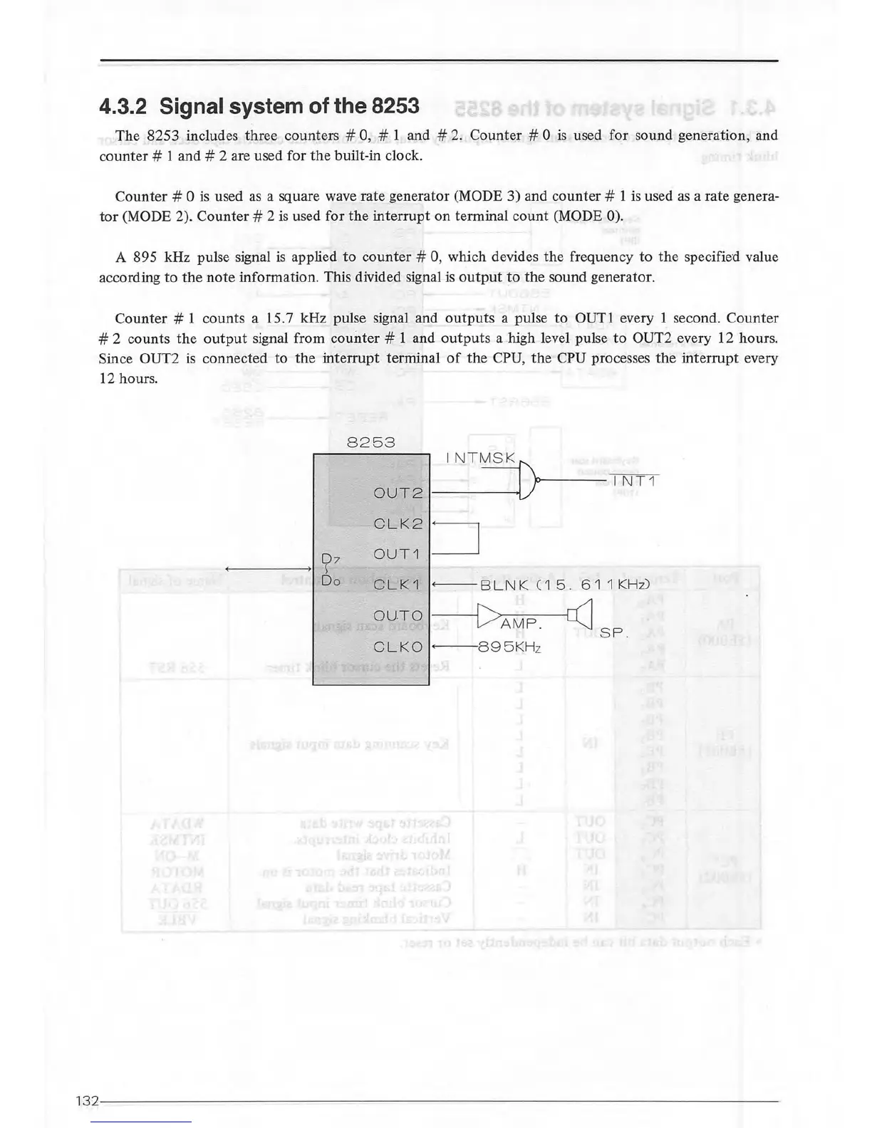
The 8253 includes three counters # 0, # 1 and #
2.
Counter # 0
is
used
for
sound generation, and
counter#
1 and # 2 are used for
the
built-in clock.
Counter#
0
is
used
as
a square wave rate generator (MODE 3) and
counter#
1 is used
as
a rate genera-
tor
(MODE 2).
Counter#
2
is
used for
the
interrupt on terminal
count
(MODE 0).
A 895 kHz pulse signal
is
applied
to
counter#
0, which devides
the
frequency
to
the
specified value
according
to
the
note
information. This divided signal
is
output
to
the
sound generator.
Counter#
1 counts a 15.7 kHz pulse signal and
outputs
a pulse to
OUTl
every 1 second. Counter
# 2 counts
the
output
signal from
counter
# 1 and
outputs
a high level pulse
to
OUT2 every 12 hours.
Since
OUT2
is
connected to the
interrupt
terminal
of
the
CPU,
the
CPU processes
the
interrupt
every
12 hours.
8253
INT
OUT2
~-
---
-V
--:-
1
--:-
N
.,.-:
T
=---o---
1
CLK2
:J
0 7
OUT1
s
Do
CLK1
B L N K C 1
5.
6 1 1
KHz)
OUTO
~SP
.
CLKO
895K
Hz
132--
----
--------
-----------------------------------------------------------