4
C: AC connector
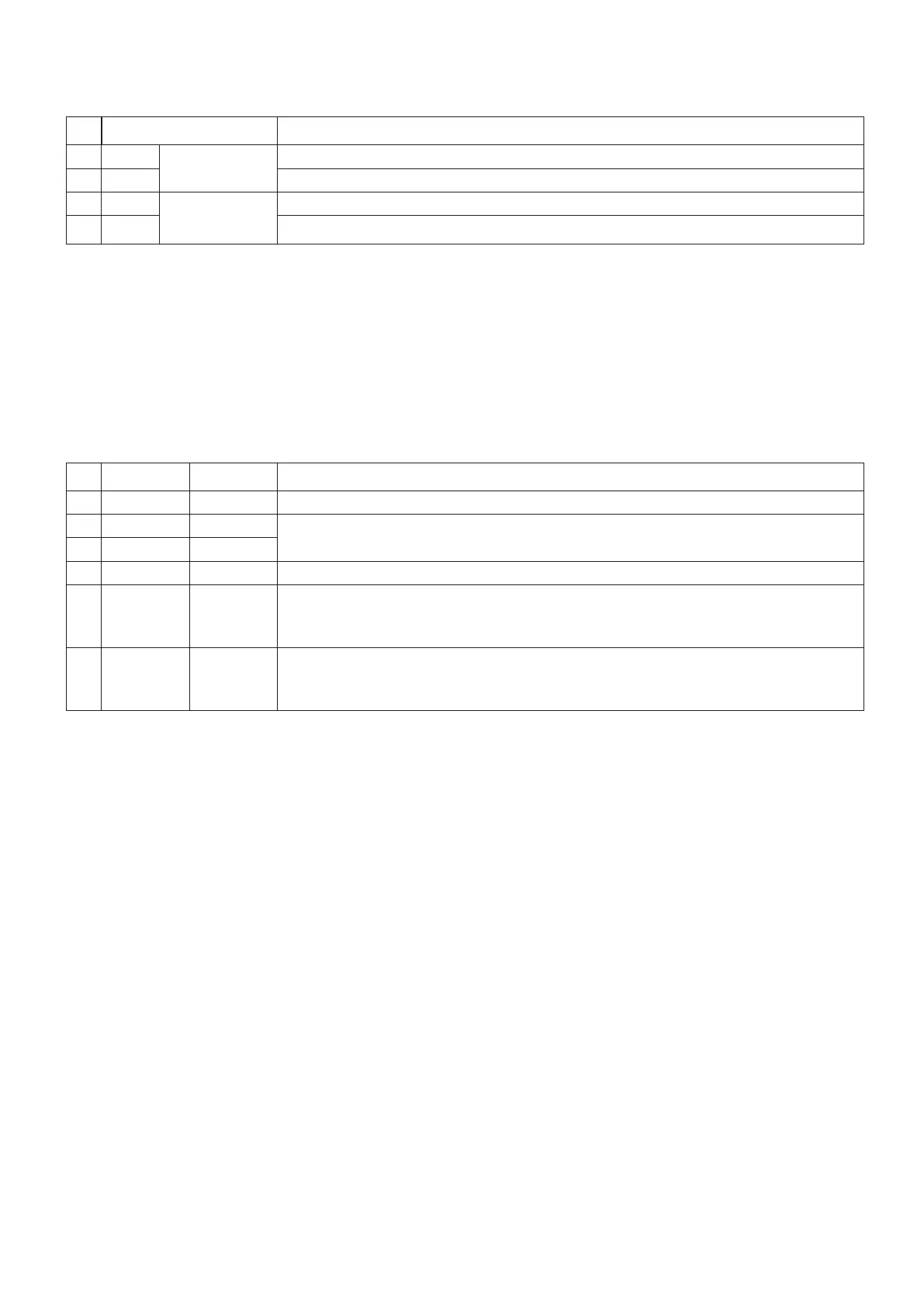
Nr Pin name Explanation
1 L
h
Supply line live ( L )
2 N Supply line neutral ( N )
3 L
i
Connect to LED device live ( L )
4 N Connect to LED device neutral ( N )
Note
The protective ground wire (PE) must be connected with a seperate clamp
D: RS-485 Termination switch
Set the switch to ON, for the first and the last device in the chain
For the other devices set the switch to OFF.
E: Control connector
Nr Pin name Name Explanation
1 + DC12 V Connect to +12V DC power supply
2 B RS-485(-)
Use this connector when controlling the device using RS-485 communication
3 A RS-485(+)
4
┴
GND Common for 1, 5 and 6
5
h
Control
In
Switch AC OUT with a potential free switch contact
Contact Closes: Switch the AC OUT ON
Contact Opens: Switch the AC OUT OFF
6
i
Control Out The “Control Out” drives the “Control In” of the next device. The next device switches
the “AC OUT” ON with a delay of aprox. 1.8 sec (see schematic on page 6 - I/O port
control)