6
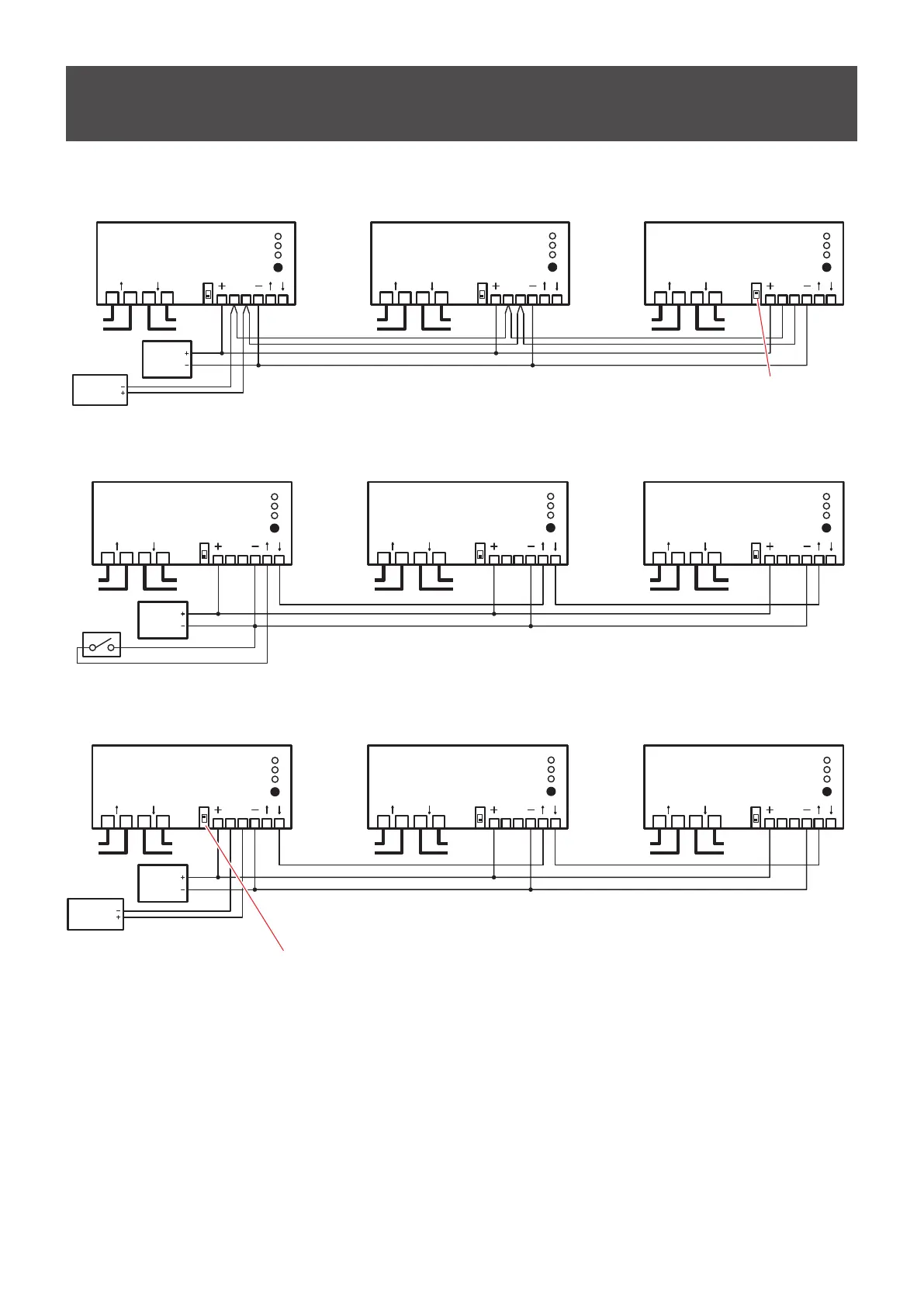
Wiring Diagrams
RS-485 control
Device -1
Device -2
Device -3
ON/OFF
REMOTE
STATUS
MODE
ON/OFF
REMOTE
STATUS
MODE
ON/OFF
REMOTE
STATUS
MODE
Power
Supply
+12V
to LED
Screen
(Line 1)
from
POWER BOX
(Line 2)
to LED
Screen
(Line 2)
from
POWER BOX
(Line 3)
to LED
Screen
(Line 3)
RS-485
Controller
AB
LNLN
AB
LNLN
AB
LNLN
Set the termination switch to on.
(1)
I/O port control
Power
Supply
+12V
to LED
Screen
(Line 1)
from
POWER BOX
(Line 2)
to LED
Screen
(Line 2)
from
POWER BOX
(Line 3)
to LED
Screen
(Line 3)
Switch
AB
LNLN
ABLNLN ABLNLN
Device -1
Device -2
Device -3
ON/OFF
REMOTE
STATUS
MODE
ON/OFF
REMOTE
STATUS
MODE
ON/OFF
REMOTE
STATUS
MODE
(1)
RS-485 control + I/O port control
Device -1
Device -2
Device -3
ON/OFF
REMOTE
STATUS
MODE
ON/OFF
REMOTE
STATUS
MODE
ON/OFF
REMOTE
STATUS
MODE
Power
Supply
+12V
to LED
Screen
(Line 1)
from
POWER BOX
(Line 2)
to LED
Screen
(Line 2)
from
POWER BOX
(Line 3)
to LED
Screen
(Line 3)
RS-485
Controller
AB
LNLN
AB
LNLN
AB
LNLN
Set the termination switch to on.
(2)
(1)
Note
(1), (2), (3) Power Supply, RS-485 Controller and Switch are not included in the scope of delivery and has to be purchased
externally from a third-party provider.
(2) The RS-485 Controller can be any device, which communicates via RS-485 protocol
(e.g. PC, Mediacontroller, KNX or EIB device)
(3) Switch can be for example a potential free output of an KNX or EIB device.