q
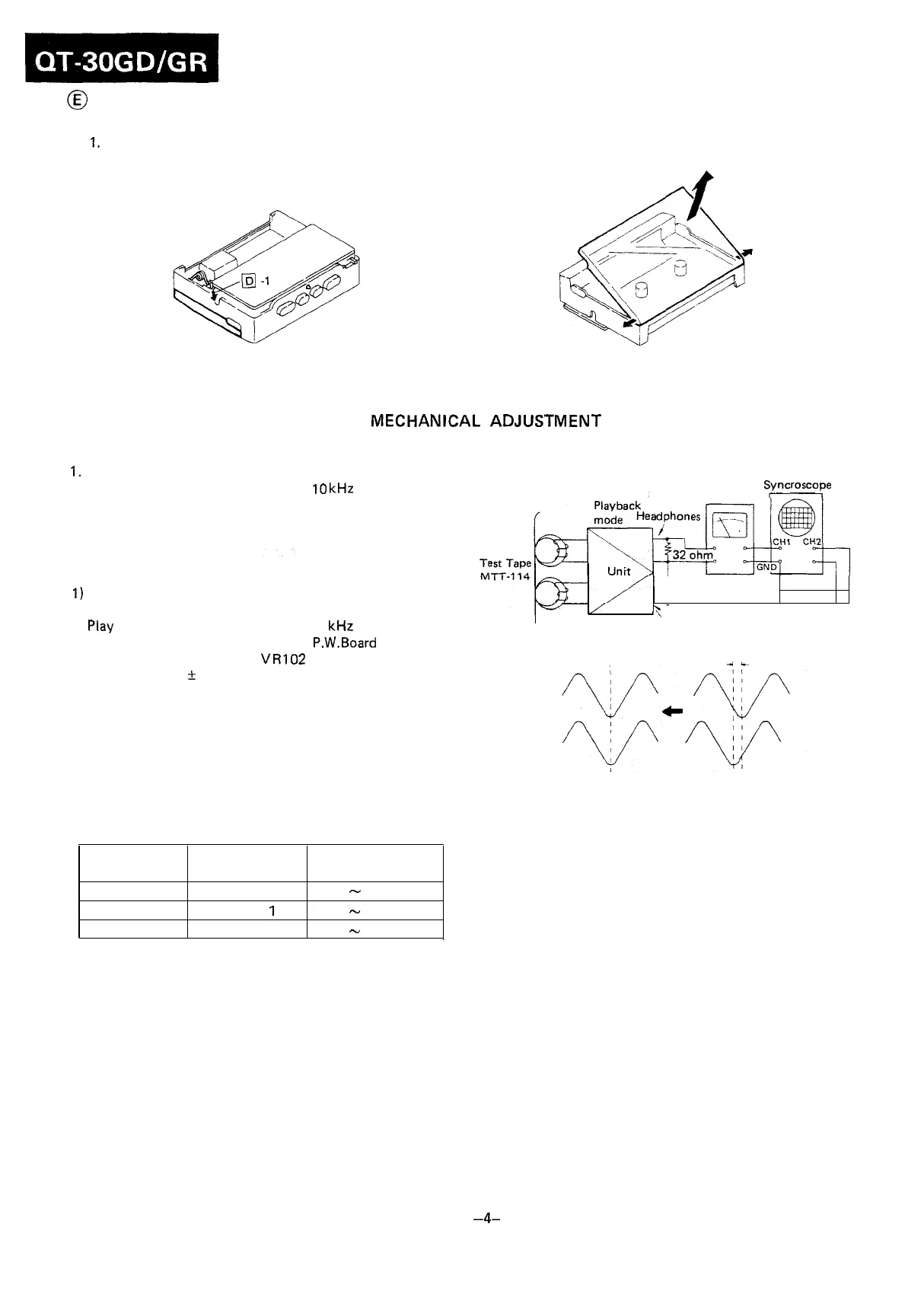
REMOVAL OF CASSETTE COMPARTMENT
1.
Remove the cassette compartment spring.
2. Open the cassette compartment in the arrow direction
to take it off.
Figure 4-l Figure 4-2
MECHANICAL
ADJUSTMENT
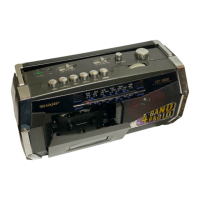
PLAYBACK HEAD AZIMUTH ADJUSTMENT
1.
Connect instruments as shown in Fig. 4-3.
2. Play a test tape (TEAC, MTT-114, 10
kHz
prerecorded).
3. Adjust the head azimuth adjusting screw so that sine
waveform attains the maximum.
TAPE SPEED ADJUSTMENT
1)
Connect a wow/flutter meter, across a 32 ohm resistor,
to the headphones jack.
2) Play a test tape (TEAC, MTT-111, 3
kHz
prerecorded).
3) Put a plastic screwdriver on the P.W.Board and adjust
the semi-variable resistor
VR102
so that the output fre-
quency is 3000 + 20 Hz on the wow/flutter meter.
TORQUE CHECK AT PLAY, FAST FORWARD AND
REWIND MODES
Put a torque meter cassette in the cassette compartment
of the set, and see that the measured torque in each mode
is normal as shown in Table 4.
Mode
Playback
Fast-forward
Rewind
Torque meter
cassette
TW-2111
TW-223
1
TW-223 1
Measured torque
35
-
55
g-cm
50
-
100
g-cm
50
-
100
g-cm
Table 4
Dual-trace
Electronic Voltmeter
Syncroscope
32
ohm
\-
’
’
Headphones
as small as possible
4L
Figure 4-3
TAPE TENSION CHECK
Put a tape tension meter cassette (TW-2412) in the cassette
compartment of the set, and see that measured tape tension
reading is more than 90 g-cm.
-4-