26
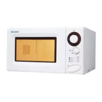
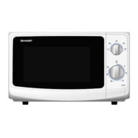
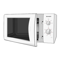
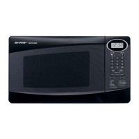
R-200BK
R-200BW
6
45
1
2
3
6
45
1
2
3
A
B
C
D
E
F
G
H
A
B
C
D
E
F
G
H
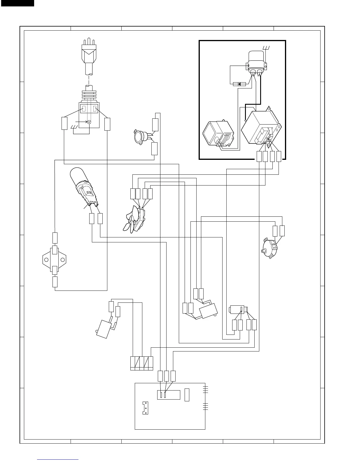
Figure S-1. Pictorial Diagram
WHT
RED
WHT
WHT
HIGH VOLTAGE COMPONENTS
MAGNETRON
HIGH
VOLTAGE
CAPACITOR
H.V.
RECTIFIER
MONITOR
SWITCH
TURNTABLE
MOTOR
FAN MOTOR
OVEN LAMP
& SOCKET
GRY
SECONDARY
INTERLOCK SWITCH
COM
COM
ORG
GRY
RED
GRY
N.C.
N.O.
GRY
GRY
ORG
WHT
C/T FUSE
POWER SUPPLY CORD
120V 60Hz
GRD
H
N
NOTE:
The grounding conductor of
the power supply cord has
been grounded by power
supply cord fixing screw.
The screw must allways be
kept tight.
NOTE:
The neutral (WHT) wire must be
connected to the terminal with "N"
mark on the power supply cord.
RED
WHT
DOOR
SENSING SWITCH
GRY
ORG
ORG
POWER
TRANSFORMER
HIGH VOLTAGE
WIRE B
BLK
Blue Mark
NOTE: Hot (RED) wire must
be connected to the terminal
with blue mark on the oven
light socket.
WHT
GRY
CONTROL PANEL
GRY
ORG
WHT
BLK
MAGNETRON
THERMAL CUT-OUT
ORG
SP1
PRIMARY
INTERLOCK
RELAY
CN-A
RY1
ORG
RED
ORG
WHT
CN-A
2
GRY
GRY
1
3
4
5
ORG
ORG
N.O.
COM