EasyManua.ls Logo

Sharp R-203FW

Sharp R-203FW
36 pages
To Next Page IconTo Next Page
Loading...
35
R-201FK/W
R-203FW
R-205FW
R-206FW
MICROWAVE OVEN
In the interest of user-safety the oven should be restored to its original
condition and only parts identical to those specified should be used.
WARNING TO SERVICE PERSONNEL: Microwave ovens con-
tain circuitry capable of producing very high voltage and
current, contact with following parts may result in a severe,
possibly fatal, electrical shock. (High Voltage Capacitor, High
Voltage Power Transformer, Magnetron, High Voltage Recti-
fier Assembly, High Voltage Harness etc..)
TABLE OF CONTENTS
Page
PRECAUTIONS TO BE OBSERVED BEFORE AND DURING SERVICING TO
AVOID POSSIBLE EXPOSURE TO EXCESSIVE MICROWAVE ENERGY ...................INSIDE FRONT COVER
BEFORE SERVICING ......................................................................................................INSIDE FRONT COVER
WARNING TO SERVICE PERSONNEL................................................................................................................ 1
MICROWAVE MEASUREMENT PROCEDURE ................................................................................................... 2
FOREWORD AND WARNING............................................................................................................................... 3
PRODUCT SPECIFICATIONS ..............................................................................................................................4
GENERAL INFORMATION................................................................................................................................... 4
OPERATION ..........................................................................................................................................................6
TROUBLESHOOTING GUIDE ..............................................................................................................................9
TEST PROCEDURE ............................................................................................................................................10
TOUCH CONTROL PANEL ................................................................................................................................. 18
COMPONENT REPLACEMENT AND ADJUSTMENT PROCEDURE ................................................................ 22
PICTORIAL DIAGRAM ........................................................................................................................................ 28
CONTROL PANEL CIRCUIT ...............................................................................................................................29
PRINTED WIRING BOARD .................................................................................................................................30
PARTS LIST ........................................................................................................................................................30
PACKING AND ACCESSORIES .........................................................................................................................34
S1201R201FPW/
R-201FK/W
R-203FW
R-205FW
R-206FW
MODELS
SERVICE MANUAL
SHARP CORPORATION
This document has been published to be used for after
sales service only.
The contents are subject to change without notice.
R-206FW

Questions and Answers:

Sharp R-203FW Specifications

General IconGeneral
TypeMicrowave Oven
Capacity20 Liters
TurntableYes
Turntable Diameter255 mm
ColorWhite
Power Output800W
Cooking ModesMicrowave
Defrost ModesYes

Summary

Microwave Oven Service Precautions

Before Servicing Procedures

Steps and safety checks to perform before servicing microwave ovens.

Warning to Service Personnel

Risk of Electric Shock

Warning about discharging high-voltage capacitors before servicing.

Microwave Measurement Procedure

Foreword

Product Description

Overview of the microwave oven's features and capabilities.

General Information

General operational guidelines and electrical requirements for the oven.

Operation

Description of the oven's operational sequence and modes.

Troubleshooting Guide and Test Procedure

Procedures for diagnosing and testing oven faults.

Touch Control Panel

Information and procedures related to the oven's touch control panel.

Component Replacement and Adjustment Procedure

Detailed steps for replacing and adjusting oven components.

Wiring Diagram

Schematics illustrating the oven's electrical connections.

Parts List

List of all replacement parts for the microwave oven.

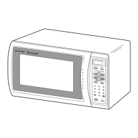
Oven Diagram

Touch Control Panel Layout

Layout and function of the oven's touch control interface.

Microwave Oven Operation

Description of Operating Sequence

Step-by-step explanation of how the oven operates.

Power Level Cooking

Explanation of variable power level settings and their ON/OFF times.

Power Output Reduction

Information on automatic power level adjustment for long cooking times.

Schematic Diagrams

Oven Schematic-Off Condition

Schematic diagram when the oven is in the off condition.

Oven Schematic-Cooking Condition

Schematic diagram when the oven is in the cooking condition.

Description and Function of Components

Door Mechanisms and Safety Switches

How the door opens and the function of door sensing and interlock switches.

Monitor Switch Function

Role of the monitor switch in detecting interlock failures.

Turntable Motor

Function of the motor that rotates the turntable for even cooking.

Troubleshooting Guide

Important Safety Reminders

Critical steps before replacing a blown C/T fuse and during troubleshooting.

Test Procedures Overview

Off Condition Problems

Troubleshooting for issues when the oven is not operating.

Cooking Condition Problems

Troubleshooting for issues during the cooking cycle.

Magnetron Assembly Test

Procedure to test the magnetron for proper function.

Test Procedures (Continued)

Power Transformer Test

Procedure to test the power transformer for continuity and resistance.

Microwave Output Power Test

Procedure to measure magnetron power output using a water temperature rise test.

Test Procedures (Continued)

High Voltage Component Tests

Procedures for testing rectifier, capacitor, and temperature fuse.

Interlock Switch Test

Procedure to test the secondary interlock switch operation.

Test Procedures (Continued)

Primary Interlock System Test

Tests for door sensing switch and primary interlock relay.

Monitor Switch Test

Procedure to test the monitor switch for proper operation.

Test Procedures (Continued)

Blown CT Fuse Test

Procedure for testing and replacing a blown C/T fuse.

Touch Control Panel Assembly Test

Procedures for testing the touch control panel and key unit.

Test Procedures (Continued)

Key Unit Test

Procedure to determine if the key unit or control unit is faulty.

Touch Control Panel Assembly

Key Unit Function

Function and operation of the touch control panel's key unit.

Control Unit Circuits

Functions of the control unit's various circuits.

Description of LSI

Touch Control Panel Assembly Outline

Key Unit Overview

Explanation of the key unit's matrix and signal flow.

Control Unit Circuitry

Description of the control unit's circuits like reset, indicator, power source.

Servicing Procedures

Precautions for Handling Electronic Components

Safety measures for handling sensitive electronic parts like CMOS LSI.

Servicing of Touch Control Panel

Procedures for servicing the touch control panel with oven or external power.

Component Replacement and Adjustment Procedures

Warning Against High Voltage

Critical warnings about severe electrical shock hazard from high voltage parts.

Warning for Wiring

Precautions to prevent electric shock and ensure correct wiring.

Outer Case Removal

Step-by-step guide to safely remove the oven's outer case.

Component Replacement and Adjustment Procedures (Continued)

Magnetron Removal

Procedure for safely removing the magnetron from the waveguide.

High Voltage Components Removal

Procedure for removing high voltage capacitor and rectifier assembly.

Power Transformer Removal

Procedure for removing and reinstalling the power transformer.

Component Replacement and Adjustment Procedures (Continued)

Control Panel Assembly Removal

Procedure for removing the oven's control panel assembly.

Graphic Sheet and Membrane Switch Replacement

Steps for replacing the graphic sheet and membrane switch.

Turntable Motor Removal

Procedure for removing and reinstalling the turntable motor.

Component Replacement and Adjustment Procedures (Continued)

Cooling Fan Motor Removal

Procedure for removing and installing the cooling fan motor.

Door Sensing SwitchInterlockMonitor Switch Removal

Procedure for removing door switches and monitor switch.

Component Replacement and Adjustment Procedures (Continued)

Door Switch and Monitor Switch Adjustment

Adjusting door switches and monitor switch for proper operation.

Door Replacement Procedure

Procedure for disassembling and replacing the oven door panel.

Component Replacement and Adjustment Procedures (Continued)

Sealer Film Installation

Procedure for applying the sealer film to the door panel.

Pictorial Diagram

Control Panel Circuit Diagram

Parts List - Electric Parts

Electric Parts List

Part numbers and descriptions for electrical components.

Parts List - Other Sections

Component Parts Lists

Part numbers for cabinet, control panel, oven, and door components.

Miscellaneous and Hardware

Lists for miscellaneous items and screws, nuts, and washers.

How to Order Replacement Parts

Oven and Cabinet Parts Diagram

Packing and Accessories

Related product manuals