R-2197
25
of the monitor switch is pressed with the door closed.
4. Secure the screws with washers firmly.
5. Check the operation of all switches. If each switch has
not activated with the door closed, loosen screw and
adjust the latch hook position.
After adjustment, check the following.
1. In and out play of door remains less than 0.5mm when
in the latched position. First check upper position of
latch hook, pushing and pulling upper portion of door
toward the oven face. Then check lower portion of the
latch hook, pushing and pulling lower portion of the
door toward the oven face. Both results (play in the
door) should be less than 0.5mm.
2. The 1st. latch switch, 2nd. latch switch and stop switch
interrupt the circuit before the door can be opened.
3. Monitor switch contacts close when door is opened.
4. Re-install outer case and check for microwave leakage
around door with an approved microwave survey meter.
(Refer to Microwave Measurement Procedure.)
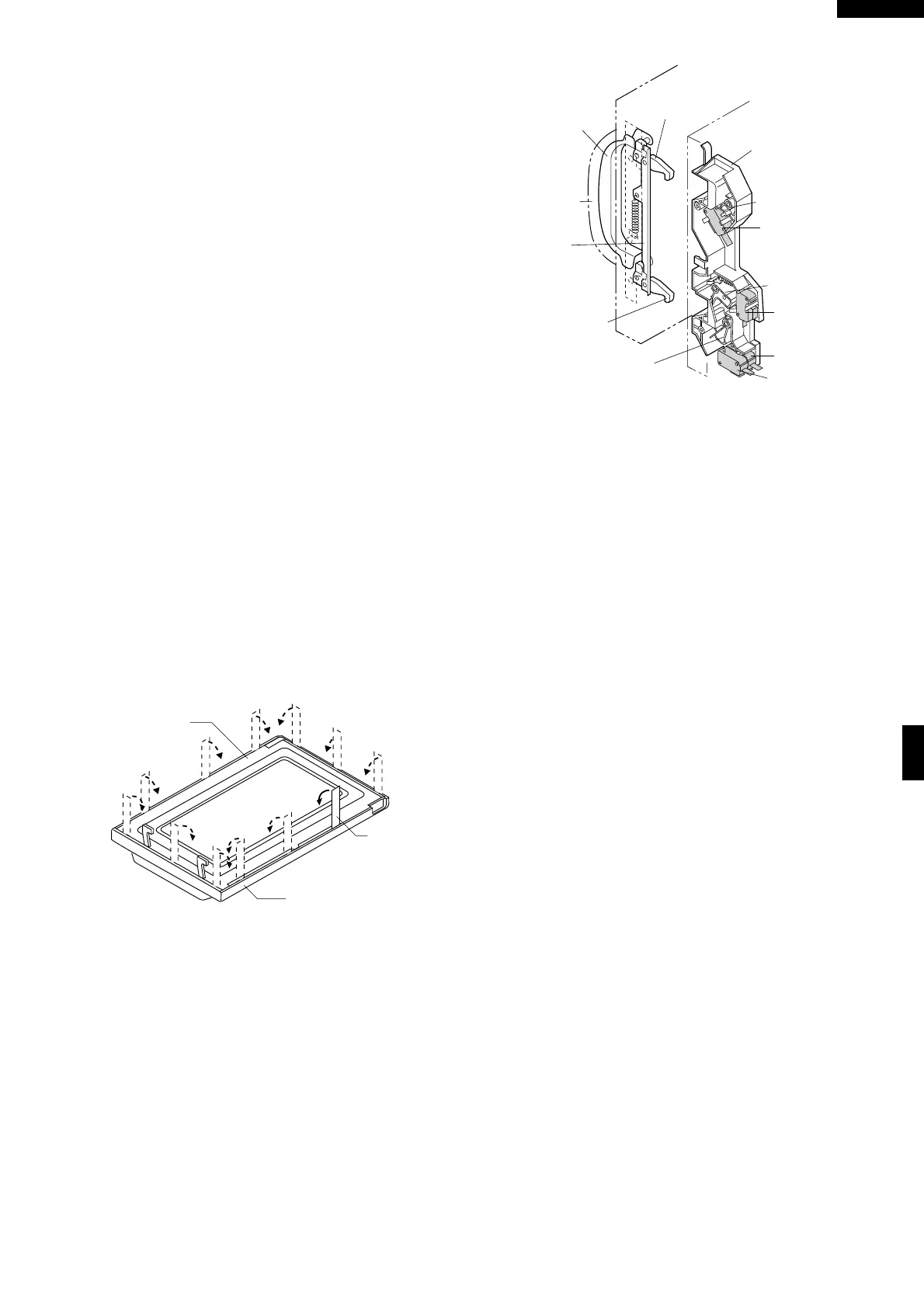
Figure C-5. Latch Switch Adjustments
CHOKE COVER
1. Disconnect the oven from the power supply.
2. Open the oven door and wedge it open.
3. Insert a putty knife (thickness of about 0.5mm) into the
gap between the choke cover and door frame as shown
in Figure C-6 to free engaging parts.
4. Pry the choke cover by inserting a putty knife as shown
in Figure C-6.
5. Release choke cover from door panel.
6. Now choke cover is free.
Figure C-6. Door Disassembly
7. Release two (2) pins of door panel from two (2) holes
of upper and lower oven hinges by lifting up.
8. Now, door sub assembly is free from oven cavity.
DOOR PANEL REMOVAL
9. Remove the four (4) screws holding the door panel to
the door frame.
10.Release door panel from seven (7) tabs of door frame
by sliding door panel downward.
11.Now, the door panel is free.
DOOR HANDLE REMOVAL
12.Release the latch spring from the tab of the latch angle
assembly.
13.Remove the two (2) screws holding the door handle
and the latch angle assembly through the door frame.
14.Now, door handle is free.
DOOR PARTS REPLACEMENT
LATCH HEADS REMOVAL
15.Remove the one (1) screw holding the latch angle
assembly to the door frame.
16.Remove the latch angle assembly together with the
latch lever, latch spring and the upper and lower latch
heads from the door frame.
17.Release the latch lever together with the latch spring
and the latch heads from the latch angle assembly.
18.Release the two (2) latch heads from the latch lever.
19.Now, the upper and lower latch heads are free.
FRONT DOOR GLASS REMOVAL
(After DOOR PANEL REMOVAL)
12.Remove the four (4) screws holding the glass stopper
U to the door frame and remove the glass stopper U.
13.Remove the two (2) screws holding the glass stopper
R to the door frame and remove the glass stopper R.
14.Slide the front door glass left at first and then slide
upwards to release it from the tabs holding it.
17.Now, the front door glass is free
DOOR CASE REMOVAL
(After DOOR PANEL REMOVAL)
12.Straighten all tabs of the door case holding the door
case to the door frame.
13.Release door case from the door frame.
17.Now, the door case is free
NOTE: At this moment, the door badge is attached on the
door case.
RE-INSTALL OF THE DOOR
1. Re-install all door parts except the choke cover.
2. Catch two (2) pins of door panel on two (2) holes of
upper and lower oven hinges.
3. Re-install choke cover to door panel by pushing.
NOTE: After any service to the door;
(A) Make sure that door sensing switch and second-
ary interlock switch are operating properly. (Re-
fer to chapter "Test Procedures".).
Latch Hook
Latch Switch
Lever A
Latch Switch
Lever B
Latch Switch
Lever C
Latch Head
Latch Head
Handle
Lever
Door
Handle
Latch
Lever
2nd. Latch Switch
Monitor
Switch
Stop Switch
1st . Latch Switch
Putty Knife
Door Frame
Choke Cover