R-2197
5
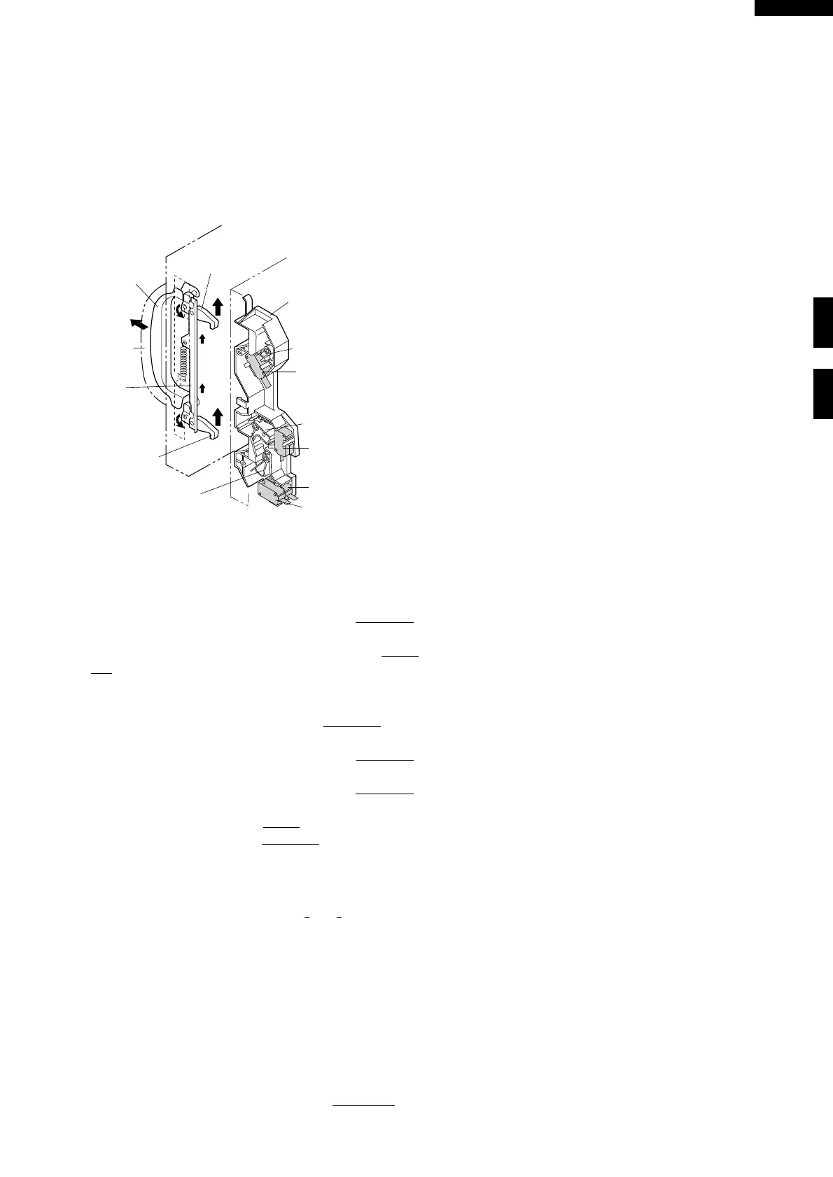
DOOR OPEN MECHANISM
The door is opened by grasping the door handle, refer to
Figure D-1.
When the door handle is grasped, the handle lever is
pulled. And then the upper and lower latch heads are
moved upward by the handle lever, and they are re-
leased from the latch hook. Now the door will open.
Figure D-1. Door Open Mechanism
1ST. LATCH SWITCH AND 2ND. LATCH SWITCH
AND STOP SWITCH
1. When the oven door is closed, the contacts (COM-NO)
of each switch must be closed.
2. When the oven door is opened, the contacts (COM-
NO) of each switch must be opened.
MONITOR SWITCH
1. When the door is closed, the contacts (COM-NC) must
be opened.
2. When the door is opened, the contacts (COM-NC)
must be closed.
3. If the oven door is opened and the contacts (COM-NO)
of the 1st. latch switch, 2nd. latch switch and relay
(RY2) fail to open, the fuse M10A blows immediately
after closing the contacts (COM-NC) of the monitor
switch.
CAUTION: BEFORE REPLACING A BLOWN FUSE
M10A TEST THE 1ST. LATCH SWITCH, 2ND.
LATCH SWITCH, RELAY (RY2), MONITOR
SWITCH AND MONITOR RESISTOR FOR
PROPER OPERATION. (REFER TO CHAP-
TER “TEST PROCEDURE”).
FUSE M10A 250V
1. If the wire harness or electrical components are short-
circuited, this fuse blows to prevent an electric shock or
fire hazard.
2. This fuse blows when the 1st. latch switch, 2nd. latch
switch and relay (RY2) remain closed with the oven
door open and when the contacts (COM-NC) of
monitor switch closes.
FUNCTION OF IMPORTANT COMPONENTS
HIGH VOLTAGE FUSE 0.75A
The high voltage fuse blows when the high voltage rectifier
or the magnetron is shorted.
THERMAL CUT-OUT 145˚C (MAGNETRON)
This thermal cut-out protects the magnetron against over-
heating. If the temperature goes up higher than 145˚C
because the fan motor is interrupted or the ventilation
openings are blocked, the thermal cut-out will open and
line voltages to the high voltage transformer will be cut off
and the operation of the magnetron will be stopped. The
thermal cut-out will not resume.
THERMAL CUT-OUT 125˚C (OVEN)
The thermal cut-out located on the top of the oven cavity
is designed to prevent damage to the oven if the food in the
oven catches fire due to over heating produced by im-
proper setting of the cooking time or failure of control unit.
Under normal operation, the oven thermal cut-out re-
mains closed. However, when abnormally high tempera-
tures are reached within the oven cavity, the oven thermal
cut-out will open at 125˚C causing the oven to shut down.
The thermal cut-out will not resume.
MONITOR RESISTOR
The monitor resistor prevents the fuse M10A bursting
when the fuse M10A blows due to the operation of the
monitor switch.
NOISE FILTER
The noise filter assembly prevents radio frequency inter-
ference that might flow back in the power circuit.
ANTENNA MOTOR
The antenna motor rotates the stirrer antenna located on
the bottom of the oven cavity, so that the food on the
ceramic shelf is cooked evenly during cooking. The an-
tenna motor may turn in either direction.
COOLING FAN MOTOR
The cooling fan motor drives a blade which draws exter-
nal cool air. This cool air is directed through the air vanes
surrounding the magnetron and cools the magnetron.
This air is channelled through the oven cavity to remove
steam and vapors given off from the heating food. It is
then exhausted through the exhausting air vents at the
oven cavity.
Latch Hook
Latch Switch
Lever A
Latch Switch
Lever B
Latch Switch
Lever C
Latch Head
Latch Head
Handle
Lever
Door
Handle
Latch
Lever
2nd. Latch Switch
Monitor
Switch
Stop Switch
1st . Latch Switch