19
R-25AM
Pin No. Signal I/O Description
DESCRIPTION OF LSI
LSI(IXA222DR)
The I/O signal of the LSI(IXA222DR) is detailed in the following table.
1 VCC IN Power source voltage: GND.
VC voltage of power source circuit input. Connected to GND.
2 VEE IN Anode (segment) of Fluorescent Display light-up voltage: -35V.
Vp voltage of power source circuit input.
3 AVSS IN Reference voltage input terminal.
A reference voltage applied to the A/D converter in the LSI. Connected to DC. (-5V)
4 VREF IN Reference voltage input terminal.
A reference voltage applied to the A/D converter in the LSI. Connected to GND.
5-6 AN7-AN6 IN Terminal to switch the specification.
7 AN5 IN Temperature measurement input: EXHAUST THERMISTOR
By inputting DC voltage corresponding to the temperature detected by the thermis-
tor, this input is converted into temperature by the A/D converter built into the LSI.
8 AN4 IN Input signal which communicates the door open/close information to LSI.
Door closed; "H" level signal (0V).
Door opened; "L" level signal (-5.0V).
9 AN3 - Terminal not used.
10 AN2 IN Temperature measurement input: MAGNETRON THERMISTOR TH2.
By inputting DC voltage corresponding to the temperature detected by the thermis-
tor, this input is converted into temperature by the A/D converter built into the LSI.
11 AN1 IN Temperature measurement input: MAGNETRON THERMISTOR TH1.
By inputting DC voltage corresponding to the temperature detected by the thermis-
tor, this input is converted into temperature by the A/D converter built into the LSI.
12 AN0 - Terminal not used.
13-14 P55-P54 - Terminal not used.
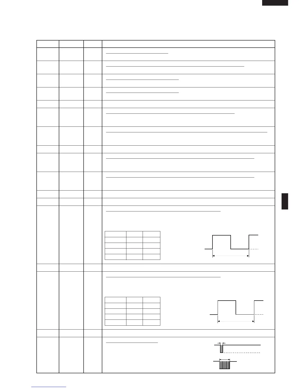
15 P53 OUT Magnetron (MG1) high-voltage circuit driving signal.
To turn on and off the cook relay. In 100% power level operation, "L" level during
cooking; "H" level otherwise. In other power level operation (50, 20 or 10%), "H" and
"L" level is repeated according to power level.
Power level ON OFF
100% 48sec. 0sec.
50% 26sec. 22sec.
20% 12sec. 36sec.
10% 8sec. 40sec.
16 P52 - Terminal not used.
17 P51 OUT Magnetron (MG2) high-voltage circuit driving signal.
To turn on and off the cook relay. In 100% power level operation, "L" level during
cooking; "H" level otherwise. In other power level operation (50, 20 or 10%), "H" and
"L" level is repeated according to power level.
Power level ON OFF
100% 48sec. 0sec.
50% 26sec. 22sec.
20% 12sec. 36sec.
10% 8sec. 40sec.
18 P50 - Terminal not used.
19 P47 OUT Signal to sound buzzer.
This signal is to control the 2.0kHz
continuous signal.
A: Switch touch sound.
B: Completion sound.
GND
-5V
48 sec.
OFF
ON
GND
-5V
48 sec.
OFF
ON
A
B
0.12 sec
2.4 sec
GND
-5V
 Loading...