Do you have a question about the Sharp R-370EK and is the answer not in the manual?
Precautions to prevent excessive microwave energy exposure during servicing.
Steps to prepare for servicing the microwave oven.
Steps to prepare for servicing, including discharging the capacitor.
Procedures to follow after testing and completing repairs.
Specifies requirements, test setup, and preparation for microwave leakage testing.
Step-by-step guide for performing the microwave leakage measurement.
Important warnings and dangers related to high voltage components during servicing.
Lists specific components that pose an electrical shock hazard.
Details power, dimensions, control system, and safety standards.
Instructions for proper grounding and electrical supply for safe operation.
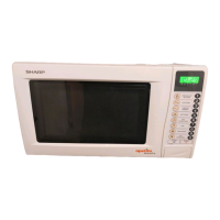
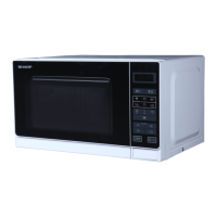
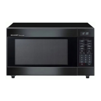
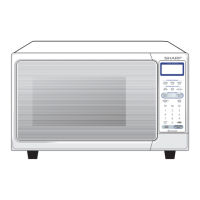
Visual guide to oven parts and layout of the touch control panel.
Describes the sequence of operation and variable power level cooking.
Explains the sensor cooking mode, its operation, and an example.
Provides circuit diagrams for the oven in off and cooking states.
Details the door opening mechanism, safety switches, and monitor circuits.
Explains thermal cut-outs, monitor fuse, and motor functions.
Guidelines for troubleshooting, including power disconnection and completion steps.
Focuses on troubleshooting a blown monitor fuse and related components.
Procedures for testing magnetron assembly, output power, and power transformer.
Procedures for testing high voltage rectifier, capacitor, and thermal protection components.
Procedures for testing various switches, the secondary interlock relay, and monitor switch.
Procedures for testing the monitor fuse and diagnosing control unit symptoms.
Details on control unit symptoms and procedures for testing the key unit.
Procedures for testing relays, Compu Defrost, and printed wiring board foil patterns.
Procedures for testing the AH sensor's initial condition and via a water load test.
Methods to verify AH sensor and control unit functionality through specific tests.
Details of the sensor dummy resistor circuit diagram for testing purposes.
Describes control unit composition, LSI signals, and their functions.
Further details on LSI signals, LCD interface, and power connections.
Explains the structure and operational principle of the absolute humidity sensor.
Details the detector circuit for the absolute humidity sensor.
Precautions for handling sensitive electronic components like CMOS LSI.
Procedures for servicing the touch control panel with oven or external power.
Warnings and precautions related to high voltage and wiring during component replacement.
Step-by-step guide for removing the oven's outer case and performing initial checks.
Procedures for removing the oven cavity, power transformer, and HV rectifier/capacitor.
Procedures for removing the magnetron, oven lamp, and fan motor.
Procedures for removing the power unit, turntable motor, and related connectors.
Procedures for adjusting door interlock switches and replacing the oven door.
Steps for disassembling and reinstalling the oven door assembly.
Procedure for applying the sealer film to the door panel.
Procedures for removing individual door parts like panel, latch, CPU unit, and harness.
Provides a visual representation of the oven's wiring connections for service.
Lists all replaceable parts with reference numbers, descriptions, and quantities.
Details the packing materials and accessories included with the oven for shipping.
Continues the comprehensive list of replacement parts for various sections of the oven.
Illustrates the location and assembly of door components and miscellaneous parts.
Precautions to prevent excessive microwave energy exposure during servicing.
Steps to prepare for servicing the microwave oven.
Steps to prepare for servicing, including discharging the capacitor.
Procedures to follow after testing and completing repairs.
Specifies requirements, test setup, and preparation for microwave leakage testing.
Step-by-step guide for performing the microwave leakage measurement.
Important warnings and dangers related to high voltage components during servicing.
Lists specific components that pose an electrical shock hazard.
Details power, dimensions, control system, and safety standards.
Instructions for proper grounding and electrical supply for safe operation.
Visual guide to oven parts and layout of the touch control panel.
Describes the sequence of operation and variable power level cooking.
Explains the sensor cooking mode, its operation, and an example.
Provides circuit diagrams for the oven in off and cooking states.
Details the door opening mechanism, safety switches, and monitor circuits.
Explains thermal cut-outs, monitor fuse, and motor functions.
Guidelines for troubleshooting, including power disconnection and completion steps.
Focuses on troubleshooting a blown monitor fuse and related components.
Procedures for testing magnetron assembly, output power, and power transformer.
Procedures for testing high voltage rectifier, capacitor, and thermal protection components.
Procedures for testing various switches, the secondary interlock relay, and monitor switch.
Procedures for testing the monitor fuse and diagnosing control unit symptoms.
Details on control unit symptoms and procedures for testing the key unit.
Procedures for testing relays, Compu Defrost, and printed wiring board foil patterns.
Procedures for testing the AH sensor's initial condition and via a water load test.
Methods to verify AH sensor and control unit functionality through specific tests.
Details of the sensor dummy resistor circuit diagram for testing purposes.
Describes control unit composition, LSI signals, and their functions.
Further details on LSI signals, LCD interface, and power connections.
Explains the structure and operational principle of the absolute humidity sensor.
Details the detector circuit for the absolute humidity sensor.
Precautions for handling sensitive electronic components like CMOS LSI.
Procedures for servicing the touch control panel with oven or external power.
Warnings and precautions related to high voltage and wiring during component replacement.
Step-by-step guide for removing the oven's outer case and performing initial checks.
Procedures for removing the oven cavity, power transformer, and HV rectifier/capacitor.
Procedures for removing the magnetron, oven lamp, and fan motor.
Procedures for removing the power unit, turntable motor, and related connectors.
Procedures for adjusting door interlock switches and replacing the oven door.
Steps for disassembling and reinstalling the oven door assembly.
Procedure for applying the sealer film to the door panel.
Procedures for removing individual door parts like panel, latch, CPU unit, and harness.
Provides a visual representation of the oven's wiring connections for service.
Lists all replaceable parts with reference numbers, descriptions, and quantities.
Details the packing materials and accessories included with the oven for shipping.
Continues the comprehensive list of replacement parts for various sections of the oven.
Illustrates the location and assembly of door components and miscellaneous parts.
| Brand | Sharp |
|---|---|
| Model | R-370EK |
| Category | Microwave Oven |
| Language | English |