EasyManua.ls Logo

Sharp R-3A55 User Manual

Sharp R-3A55
40 pages
To Next Page IconTo Next Page
Page #1 background imageLoading...
Page #1 background image
R-3A55
SHARP SERVICE MANUAL
S8304 R3A55PJ/
MICROWAVE OVEN
-.- _~__
_ _
Momx R-3A55
In interests of user-safety the oven should be restored to its original condi-
TABLE OF CONTENTS
page
GENERAL
IMPORTANT INFORMATiON..
...................................................................................................
.I
WARNING
......................................................................................................................................................
1
RODUCT SPECIFICATIONS
.........................................................................................................................
2
APPEARANCE VIEW
....................................................................................................................................
3
OPERATING SEQUENCE
.............................................................................................................................
FUNCTION
OF IMPORTANT COMPONENTS’
............................................................................................
.:
TRABLESHOOTING CHART
.........................................................................................................................
7
TEST PROCEDURE
...................................................................................................................................... 9
TOUCH CONTROL PANEL
.........................................................................................................................
16
COMPONENT REPLACEMENT AND ADJUSTMENT PROCEDURE
........................................................
21
MICROWAVE MEASUREMENT ..................................................................................................................
26
WIRING DIAGRAM ......................................................................................................................................
27
PICTORIAL DIAGRAM
.............................................................................................................................
...2 8
CONTROL PANEL CIRCUIT
.......................................................................................................................
29
PRINTED WIRING BOAD
...........................................................................................................................
.30
PARTS LIST
.................................................................................................................................................
31
SHARP CORPORATION

Table of Contents

Question and Answer IconNeed help?

Do you have a question about the Sharp R-3A55 and is the answer not in the manual?

Sharp R-3A55 Specifications

General IconGeneral
CategoryCountertop
Capacity1.1 cu. ft.
Power Output1000W
Voltage120V
Weight30.9 lbs
Wattage1000 Watts

Summary

General Important Information

Product Specifications

Details electrical, dimensional, and control specifications for the microwave oven.

Appearance View

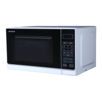
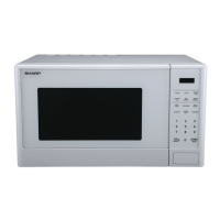
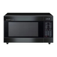
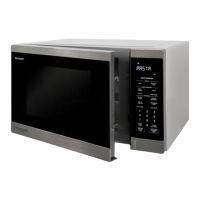
Identifies external parts and components of the microwave oven with numbered labels.

Operation Sequence

Describes the step-by-step operation and interlock switch logic of the microwave.

Function of Important Components

Explains the role and operation of key internal components like door switches and magnetron.

Troubleshooting Chart

Troubleshooting Guide

Provides guidance on diagnosing common microwave oven problems and identifying potential causes.

Test Procedures

Magnetron Test

Outlines procedures for testing the magnetron for continuity and output power.

Microwave Output Power (1 Liter Water Load)

Details method for measuring microwave output power using a 1-liter water load.

Microwave Output Power (2 Liter Water Load)

Details method for measuring microwave output power using a 2-liter water load.

Power Transformer Test

Describes continuity checks for the power transformer's primary, secondary, and filament windings.

High Voltage Rectifier Assembly Test

Explains how to test the high voltage rectifier assembly using an ohmmeter.

Asymmetric Rectifier Test

Details the procedure for testing the asymmetric rectifier for proper forward and reverse resistance.

High Voltage Capacitor Test

Provides steps for testing the high voltage capacitor for shorts, opens, or charge/discharge behavior.

Switch Test

Outlines how to test door interlock and other switches using an ohmmeter.

Thermal Cut-Out Test

Describes testing thermal cut-outs for continuity at specified temperature conditions.

Monitor Resistor Test

Details the procedure for checking the resistance of the monitor resistor.

Motor Winding Test

Explains how to test fan and turntable motor windings for resistance.

Blown Fuse F M8A

Guides on troubleshooting causes for a blown FUSE M8A, including switch and wiring checks.

Touch Control Panel Assembly Test

Provides procedures for testing the key unit and control unit of the touch panel assembly.

Relay Test

Describes how to check relay coil voltage and continuity for oven lamp and power transformer.

Touch Control Panel Assembly

Outline of Touch Control Panel

Explains the functions of the key unit and control unit in the touch panel system.

Description of LSI

LSI Signal Descriptions

Details the input/output signals and their functions for the LSI (IZA496DR) in the control panel.

Servicing

Precautions for Handling Electronic Components

Advises on handling CMOS LSI and preventing electrostatic discharge during servicing.

Servicing of Touch Control Panel

Provides procedures and precautions for servicing the microwave's touch control panel.

Component Replacement and Adjustment Procedure

Outer Case Removal

Steps for safely removing the outer cabinet of the microwave oven.

Power Transformer Removal

Procedure for removing and reinstalling the power transformer.

Magnetron Removal

Instructions for safely removing and replacing the magnetron, including RF gasket precautions.

High Voltage Rectifier and High Voltage Capacitor Removal

Details on removing HV rectifier and capacitor, with grounding precautions.

Oven Lamp and Lamp Socket Removal

Steps for removing and replacing the oven lamp and its socket.

Turntable Motor Removal

Instructions for removing and reinstalling the turntable motor.

Fan Motor Replacement

Procedure for removing and installing the fan motor assembly and fan blade.

Control Panel Assembly Removal

Steps for removing the control panel assembly from the oven.

1st. Latch Switch, 2nd. Latch Switch, Stop Switch and Monitor Switch Removal

Procedures for removing and reinstalling door interlock and monitor switches.

1st. Latch Switch, 2nd. Latch Switch and Monitor Switch Adjustment

Guidance on adjusting door switches for proper operation after servicing.

Door Replacement and Adjustment

Steps for replacing the oven door and adjusting its alignment and latching mechanism.

Door Adjustment

Specific steps for adjusting door alignment and interlock switch activation.

Door Disassembly

Microwave Measurement

Schematic

Pictorial Diagram

Control Panel Circuit

Printed Wiring Boad

Parts List

Electrical Parts

Lists electrical components with part numbers, descriptions, quantities, and codes.

Cabinet Parts

Lists external cabinet parts, including covers, cushions, and reflectors.

Control Panel Parts

Lists components related to the control panel, such as connectors, display tubes, and capacitors.

Screws, Nuts and Washers

A detailed list of screws, nuts, and washers used in the assembly and repair of the oven.

How to Order Replacement Parts

Instructions on how to correctly order replacement parts, including required information.

Oven and Cabinet Parts

Control Panel Parts

Door Parts

Miscellaneous

Packing and Accessories

Related product manuals