DOOR REPLACEMENT AND ADJUSTMENT
REMOVAL
1. Disconnect oven from power supply and remove turn-
table tray and turntable ring from oven cavity.
2. Remove the outer case cabinet, refer to “OUTER
CASE CABINET REMOVAL”.
3. Remove two (2) screws from upper oven hinge.
4.
Remove three (3) screws holding lower oven hinge and
base plate (Left) to the bottom side of the oven.
5. Push the open button and open the door slightly.
6. Release the upper oven hinge from upper door hinge
pin by pulling down the door.
Note: When the individual parts are replaced, refer to
“Door Disassembly”.;
RE-INSTALL
1.
2.
Q
d.
4.
t5.
6.
7
/
8.
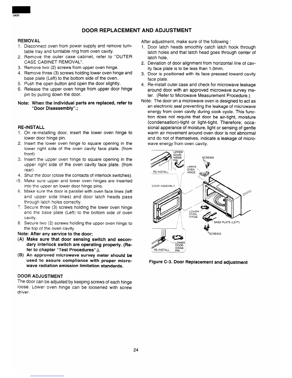
On re-installing door, insert the lower oven hinge to
lower door hinge pin.
Insert the lower oven hinge to square opening in the
lower right side of the oven cavity face plate. (from
front)
Insert the upper oven hinge to square opening in the
upper right side of the oven cavity face plate. (from
rear)
Shut the door (close the contacts of interlock switches).
Make sure upper and lower oven hinges are inserted
into the upper an lower door hinge pins.
Make sure the door is parallel with oven face lines (left
and upper side lines) and door latch heads pass
through latch holes correctly.
Secure three (3) screws holding the lower oven hinge
and the base plate (Left) to the bottom side of oven
cavity.
Secure two (2) screws holding the upper oven hinge to
the top of the oven cavity.
Note: After any service to the door;
(A) Make sure that door sensing switch and secon-
dary interlock switch are operating properly. (Re-
fer to chapter “Test Procedures”.).
(B) An approved microwave survey meter should be
used to assure compliance with proper micro-
wave radiation emission limitation standards.
After adjustment, make sure of the following :
1. Door latch heads smoothly catch latch hook through
latch holes and that latch head goes through center of
latch hole.
2. Deviation of door alignment from horizontal line of cav-
ity face plate is to be less than 1 .Omm.
3. Door is positioned with its face pressed toward cavity
face plate.
4. Re-install outer case and check for microwave leakage
around door with an approved microwave survey me-
ter. (Refer to Microwave Measurement Procedure.)
Note: The door on a microwave oven is designed to act as
an electronic seal preventing the leakage of microwave
energy from oven cavity during cook cycle. This func-
tion does not require that door be air-tight, moisture
(condensation)-tight or light-tight. Therefore, occa-
sional apperance of moisture, light or sensing of gentle
warm air movement around oven door is not abnormal
and do not of themselves, indicate a leakage of micro-
wave energy from oven cavity.
\ RE-INSTALL
/
SCREWS
SE PLATE (LEFT)
‘. LOWER
DOOR :
RE-INSTALL
HINGE I
PIN ,
*
SCREWS
Figure C-3. Door Replacement and adjustment
DOOR ADJUSTMENT
The door can be adjusted by keeping screws of each hinge
loose. Lower oven hinge can be loosened with screw
driver.
24