POSITIVE LOCK3 CONNECTOR (NO-CASE TYPE) REMOVA
Posmve iock@
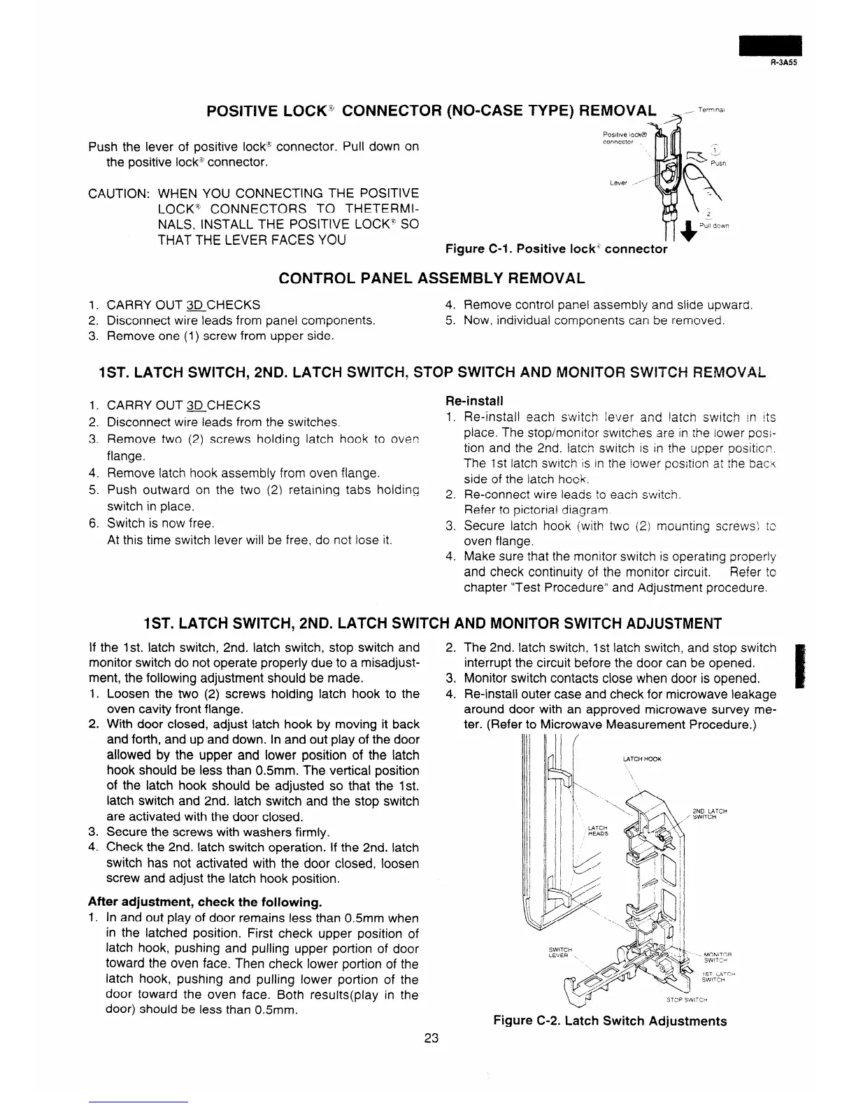
Push the lever of positive lock% connector. Pull down on
the positive lock% connector.
connector
CAUTION: WHEN YOU CONNECTING THE POSITIVE
LOCKQ CONNECTORS TO THETERMI-
NALS, INSTALL THE POSITIVE LOCK” SO
THAT THE LEVER FACES YOU
Figure C-l. Positive lock” connector
CONTROL PANEL ASSEMBLY REMOVAL
1, CARRY OUT aCHECKS
2. Disconnect wire leads from panel components.
3. Remove one (1) screw from upper side.
4. Remove control panel assembly and slide upward.
5. Now, individual components can be removed.
1ST. LATCH SWITCH, 2ND. LATCH SWITCH, STQP SWITCH AND MONITOR SWITCH REMOVAL
1. CARRY OUT QCHECKS
2. Disconnect wire leads from the switches.
3. Remove two (2) screws holding latch hook to oven
flange.
4. Remove latch hook assembly from oven flange.
Re-install
1. Re-install each s;Nitc
h lever and !atch switch in its
place. The stop/monitor swrrches are in rhe iower posi-
tion and the 2nd. latch s&itch LS in the upper positicr.
The 1st latch switch 1s rn the iower postion at the barn
side of the iatch hook.
5. Push outward on the two (2) retaining tabs holding
switch in place.
6. Switch is now free.
At this time switch lever will be free, do not lose it.
2. Re-connect wire leads to each switch.
Refer to pictoriai diagram.
3. Secure latch hook (with two (2: mounting screws! 12
oven flange.
4. Make sure that the monitor switch is operating orooerly
and check continuity of the monitor circuit.
Refer lo
chapter “Test Procedure” and Adjustment procedure.
1ST. LATCH SWITCH, 2ND. LATCH SWITCH AND MONITOR SWITCH ADJUSTMEPIT
If the 1st. latch switch, 2nd. latch switch, stop switch and
monitor switch do not operate properly due to a misadjust-
ment, the following adjustment should be made.
1. Loosen the two (2) screws holding latch hook to the
oven cavity front flange.
2. With door closed, adjust latch hook by moving it back
and forth, and up and down. In and out play of the door
allowed by the upper and lower position of the latch
hook should be less than 0.5mm. The vertical position
of the latch hook should be adjusted so that the 1st.
latch switch and 2nd. latch switch and the stop switch
are activated with the door closed.
3. Secure the screws with washers firmly.
4. Check the 2nd. latch switch operation. If the 2nd. latch
switch has not activated with the door closed, loosen
screw and adjust the latch hook position.
After adjustment, check the following.
1. In and out play of door remains less than 0.5mm when
in the latched position. First check upper position of
latch hook, pushing and pulling upper portion of door
toward the oven face. Then check lower portion of the
latch hook, pushing and pulling lower portion of the
door toward the oven face. Both results(play in the
door) should be less than 0.5mm.
2. The 2nd. latch switch, 1 st latch switch, and stop switch
interrupt the circuit before the door can be opened.
3. Monitor switch contacts close when door is opened.
4. Re-install outer case and check for microwave leakage
around door with an approved microwave survey me-
ter. (Refer to Microwave Measurement Procedure.)
L4TCH HOOK
STOP SbVi’C?
Figure C-2. Latch Switch Adjustments
2ND LATCH
/ SWITCH
i
&
-. MOixiTCIR
/i
SWIT:I
23