15
R-3S56
DESCRIPTION OF LSI
LSI(IZA588DR):
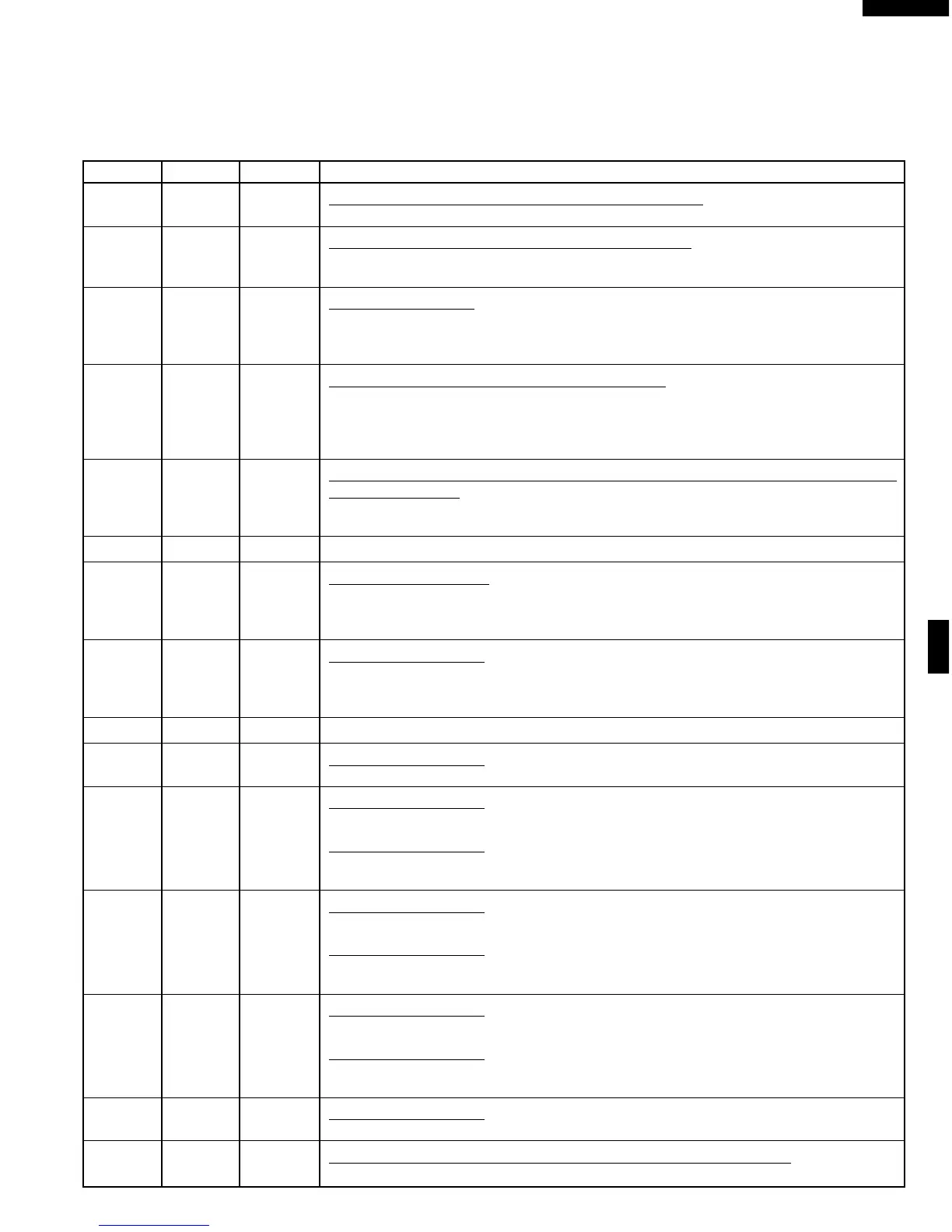
The I/O signal of the LSI(IZA588DR) is detailed in the following table.
Pin No. Signal I/O Description
1XOUT OUT Internal clock oscillation frequency control output.
Output to control oscillation input of XOUT.
2XIN IN Internal clock oscillation frequency input setting.
The internal clock frequency is set by inserting the ceramic filter oscillation circuit with
respect to XIN terminal.
3 RESET IN Auto clear terminal.
Signal is input to reset the LSI to the initial state when power is supplied. Temporarily
set to “L” level the moment power is supplied, at this time the LSI is set. Thereafter set
at “H” level.
4R70OUT Magnetron high-voltage circuit driving signal.
To turn on and off the cook relay. In Low operation, the signals holds “L” level during
microwave cooking and “H” level while not cooking. In other cooking modes
(70%,50%,30%,10%) the signal turns to “L” level and “H” level in repetition according
to the power level.
5R71OUT Oven lamp,turntable motor and cooling fan motor driving signal. (Square
Waveform : 50Hz)
To turn on and off the control relay. The pulse signal (50Hz) is delivered to the control
relay driving circuit and cook relay control circuit.
6R72OUT Terminal not used.
7 -10 R40 - R43 OUT Digit selection signal.
Refer to the touch control panel circuit about the relation between signals and digits.
Normally, one pulse is output in every synchronized signal period, and input to the light
emitting diode.
11-13 R50 - R52 OUT Segment data signal.
Refer to the touch control panel circuit for the relationship between signals and
indicators. Normally, one pulse is output in every synchronized signal period, and
input to the anode of the light emitting diode.
14 VSS IN Connected to VC.
15 R53 OUT Segment data signal.
Signal similar to R50.
16 R60 OUT Segment data signal.
Signal similar to R50.
Switch strobe signal.
Signal applied to tact switch section. A pulse signal is input to R81-R83 terminal while
one of diode D91 line switches on switch matrix is touched.
17 R61 OUT Segment data signal.
Signal similar to R50.
Switch strobe signal.
Signal applied to tact switch section. A pulse signal is input to R81-R83 terminal while
one of diode D92 line switches on switch matrix is touched.
18 R62 OUT Segment data signal.
Signal similar to R50.
Switch strobe signal.
Signal applied to tact switch section. A pulse signal is input to R81-R83 terminal while
one of diode D93 line switches on switch matrix is touched.
19 R63 OUT Segment data signal.
Signal similar to R50.
20 INT2 IN Signal synchronized with commercial source frequency(50Hz).
This is basic timing for time processing of LSI.