23
R-55TS
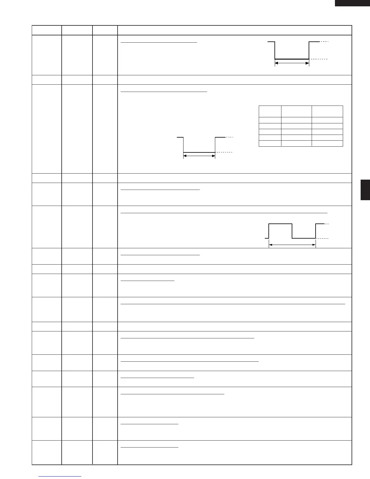
18 P50 OUT Lower heater driving signal.
To turn on and off the lower heater relay (RY4).
“L” level during GRILL2 cooking or Bake cooking.
“H” level otherwise.
19-20 P47-P46 OUT Terminal not used.
21 P45 OUT
Micro and heater driving signal.
To turn on and off the relay(RY2). “L” level during
microwave cooking, grill 1 cooking, grill 2 cooking
or bake cooking condition. “H” level otherwise. In
microwave cooking mode, the signal turns to
"H"level and "L" level in repetition according to
the power level.
22 P44 OUT Terminal not used.
23 INT1 IN
Signal coming from encoder.
When the encoder is turned, the contacts of encoder make plus signals. And plus signals are
input into INT1.
24 INT0 IN
Signal to synchronized LSI with commercial power source frequency(60Hz).
This is basic timing for time processing of LSI.
25 P41 IN Signal coming from encoder.
Signal similar to INT1.Plus signals are input into P41.
26 P40 IN Connected to VC.
27 RESET IN
Auto clear terminal.
Signal is input to reset the LSI to the initial state when power is applied. Temporarily set to
“L” level the moment power is applied, at this time the LSI is reset. Thereafter set at “H” level.
28 P71 OUT
Timing signal output terminal for temperature measurement(OVEN THERMISTOR).
“H” level (GND) : Thermistor OPEN timing.
“L” level (-5V) : Temperature measuring timing. (Bake cooking)
29 P70 OUT Terminal not used.
30 XIN IN
Internal clock oscillation frequency input setting.
The internal clock frequency is set by inserting the ceramic filter oscillation circuit with respect
to XOUT terminal.
31 XOUT OUT
Internal clock oscillation frequency control output.
Output to control oscillation input of XIN.
32 VSS IN
Power source voltage: -5V.
VC voltage of power source circuit input.
33 P27 IN
Signal coming from touch tact switch.
When any one of tact switches SW1, SW5, SW9, SW13 on switch unit matrix is touched, a
corresponding signal from P14-P17 will be input into P27. When no tact switch is touched,
the signal is held at “H” level.
34 P26 IN
Signal similar to P27.
When any one of tact switches SW2, SW6, SW10, SW14 on switch unit matrix is touched,
a corresponding signal will be input into P26.
35 P25 IN
Signal similar to P27.
When any one of tact switches SW3, SW7, SW11, SW15 on switch unit matrix is touched,
a corresponding signal will be input into P25.
Pin No. Signal I/O Description
(During Grill2 or Bake cooking)
H : GND
L
ON
OFF
Microwave cooking, Grill 1 cooking,
Grill 2 cooking or Bake cooking condition
H : GND
L
ON
OFF
16.7 msec.
H: GND
L(-5V)
ON/OFF time ratio in micro cooking
(a 32 second time base)
MICRO
COOK ON OFF
100 % 32 sec. 0 sec.
70 % 24 sec. 8 sec.
50 % 18 sec. 14 sec.
30 % 12 sec. 20 sec.
10 % 6 sec. 26 sec.