15
R-7A55(W)/(B)
R-7E45(W)/(B)
COMPONENT TEST
TEST PROCEDURES (CONT'D)
G THERMAL CUT-OUT TEST
PROCEDURE
LETTER
CARRY OUT
3D CHECKS
Disconnect the leads from the terminals of the thermal cut-out. Then using an ohmmeter, make a
continuity test across the two terminals as described in the below.
CARRY OUT 4R CHECKS
If incorrect readings are obtained, replace the thermal cut-out.
An open circuit thermal cut-out (MG)
TC1 indicates that the magnetron has overheated, this may be due
to resistricted ventilation, cooling fan failure.
An open circuit thermal cut-out (OVEN)
TC2 indicates that the oven cavity has overheated, this may be
due to no load operation.
An open circuit thermal cut-out (CONV.)
TC3 indicates that the convection fan motor winding has
overheated, this may be due to resisted ventilation or locked cooling fan or locked convection fan motor.
Table: Thermal Cut-out Test
Temperature of Temperature of Indication of
"ON" condition "OFF" condition ohmmeter
Parts Name (closed circuit). (open circuit). (When room
(˚C) (˚C) temperature is
approx. 20˚C.)
Thermal cut-out This is not resetable Above 170˚C Closed circuit
170˚C TC1 type.
Thermal cut-out This is not resetable Above 125˚C Closed circuit
125˚C TC2 type
Thermal cut-out Below 170˚C Above 190˚C Closed circuit.
190˚C TC3
H MOTOR WINDING TEST
CARRY OUT
3D CHECKS
Disconnect the leads from the motor. Using an ohmmeter, check
the resistance between the two terminals as described in the table
below.
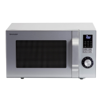
I NOISE FILTER TEST
CARRY OUT 3D CHECKS
Disconnect the leads from the terminals of
noise filter.
Using an ohmmeter, check between the ter-
minals as described in the following table.
L
N
L
L
15A
Cx
Cy
RED
WHT
F6.3A
R1
R2
If incorrect readings are absorbed, replace the noise filter unit.
CARRY OUT
4R CHECKS
MEASURING POINTS INDICATION OF OHMMETER
Between N and L Approx. 680 kΩ
Between terminal N and WHITE Short circuit
Between terminal L and RED Short circuit
L (min) Cx ± 20% Cy ± 20%
1.0mH 0.22µF 4700pF
R1: 10 MΩ ± 20%
R2 : 680 kΩ ± 20%
If incorrect readings are obtained, replace the motor.
CARRY OUT
4R CHECKS
Table: Resistance of Motor
Motors Resistance
Fan motor Approximately 182 Ω
Turntable motor Approximately 16 kΩ
Convection fan motor Approximately 163 Ω
Damper motor Approximately 16 kΩ