LATCH ASSEMBLY ADJUSTMENT
(PRIMARY AND SECONDARY INTERLOCK SWITCHES ADJUSTMENT)
The primary interlock switch and secondary interlock
switch are fixed in position, therefore individual switch
adjustment is not needed.
In case the switches do not operate properly due to a
misadjustment, the entire latch assembly should be re-
adjusted with the following manner.
1. Loosen the two (2) screws holding the latch assembly
to the mounting bracket.
2. With the door closed, adjust the position of the latch
assembly by moving it back and forward, or up and
down. The in and out play of the door allowed by the
upper and lower latch hooks should be less than
0.5 mm.
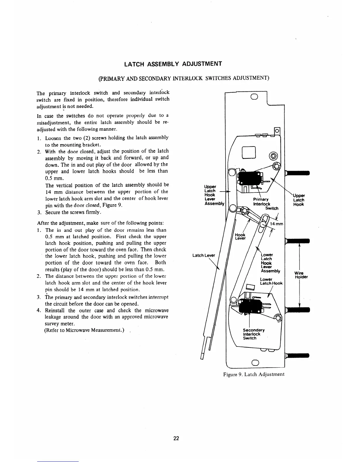
The vertical position of the latch assembly should be
14 mm distance between the upper portion of the
lower latch hook arm slot and the center of hook lever
pin with the door closed, Figure 9.
3. Secure the screws firmly.
After the adjustment, make sure of the following points:
1. The in and out play of the door remains less than
0.5 mm at latched position. First check the upper
latch hook position, pushing and pulling the upper
portion of the door toward the oven face. Then check
the lower latch hook, pushing and pulling the lower
portion of the door toward the oven face. Both
results (play of the door) should be less than 0.5 mm.
2. The distance between the upper portion of the lower
latch hook arm slot and the center of the hook lever
pin should be 14 mm at latched position.
3. The primary and secondary interlock switches interrupt
the circuit before the door can be opened.
4. Reinstall the outer case and check the microwave
leakage around the door with an approved microwave
survey meter.
(Refer to Microwave Measurement.)
.
i!Et%
Hook
Lever
Assem
Latch Lever
\
Secondary
Interlock
Switch
I
\
upper
Ii%:
Wire
Holder
Figure 9. Latch Adjustment
22