R-9H56
18
TEST PROCEDURES (CONT'D)
PROCEDURE
LETTER
COMPONENT TEST
M KEY UNIT TEST
If the display fails to clear when the STOP/CLEAR pad is depressed, first verify the flat ribbon is making
good contact, verify that the door sensing switch (stop switch) operates properly; that is the contacts are
closed when the door is closed and open when the door is open.
If the door sensing switch (stop switch) is good, disconnect the flat ribbon that connects the key unit to
the control unit and make sure the door sensing switch is closed (either close the door or short the door
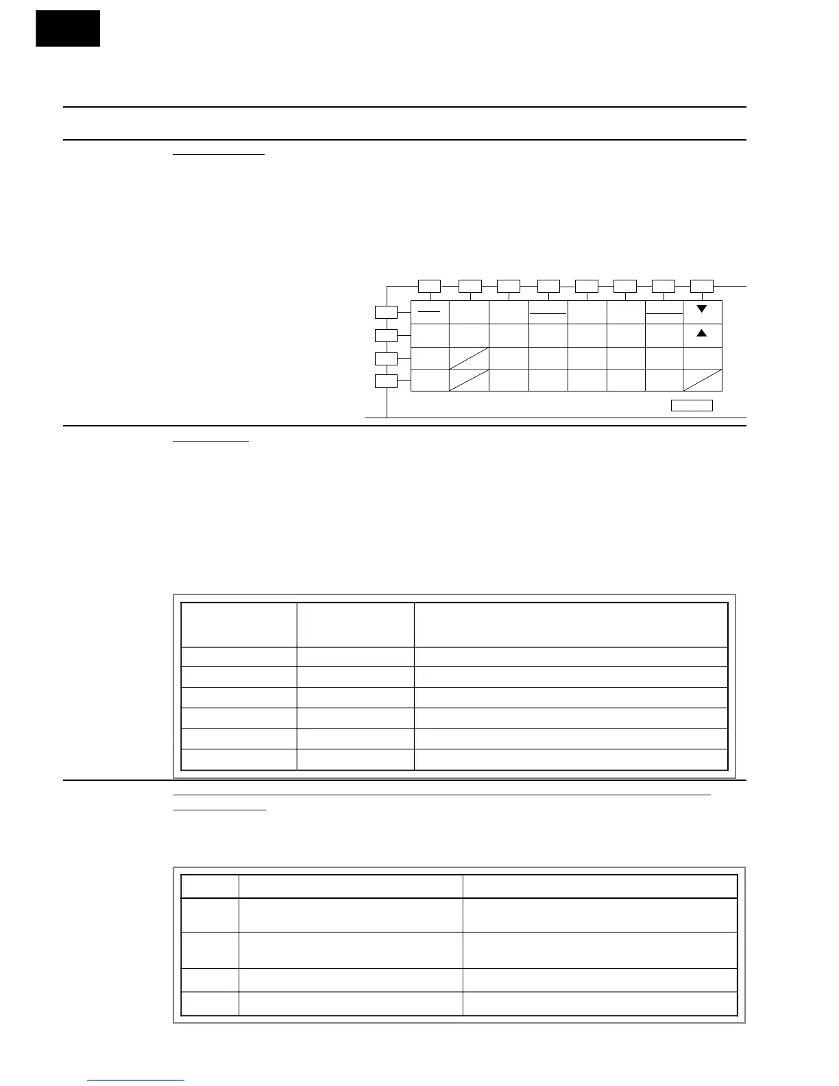
sensing switch connector). Use the key unit matrix indicated on the control panel schematic and place
a jumper wire between the pins that correspond to the STOP/CLEAR pad making momentary contact.
If the control unit responds by
clearing with a beep the key unit
is faulty and must be replaced. If
the control unit does not respond,
it is faulty and must be replaced.
If a specific pad does not re-
spond, the above method may
be used (after clearing the con-
trol unit) to determine if the con-
trol unit or key pad is at fault.
N RELAY TEST
emove the outer case and check voltage between Pin Nos. 7 and 9 of the 9-pin connector (A) on the
control unit with an A.C. voltmeter. The meter should indicate 240 volts, if not check oven circuit.
Shut-off, Cook and Heater Relay Test
These relays are operated by D.C. voltage.
Check voltage at the relay coil with a D.C. voltmeter during the microwave cooking operation or
convection cooking operation.
DC. voltage indicated ............... Defective relay.
DC. voltage not indicated ......... Check diode which is connected to the relay coil. If diode is good,
control unit is defective.
RELAY SYMBOL
OPERATIONAL
VOLTAGE
CONNECTED COMPONENTS
RY1 Approx. 19.0 V.D.C. Oven lamp/Turntable motor
RY2(COOK) Approx. 18.0 V.D.C. Power transformer
RY3(HEATER) Approx. 18.0 V.D.C. Heating element
RY4 Approx. 19.0 V.D.C. Damper motor
RY5 Approx. 19.0V.D.C. Convection motor
RY6 Approx. 19.0 V.D.C. Cooling fan motor
O PROCEDURES TO BE TAKEN WHEN THE FOIL PATTERN ON THE PRINTED WIRING BOARD
(PWB) IS OPEN.
To protect the electronic circuits, this model is provided with a fine foil pattern added to the primary on
the PWB, this foil pattern acts as a fuse. If the foil pattern is open, follow the troubleshooting guide given
below for repair.
STEPS OCCURANCE CAUSE OR CORRECTION
1 The rated voltage is not applied to POWER
terminal of CPU connector (CN-A)
Check supply voltage and oven power cord.
2 The rated voltage is applied to primary side of
power transformer.
Power transformer or secondary circuit defective. Check
and repair.
3 Only pattern at "a" is broken. *Insert jumper wire J1 and solder.
4 Pattern at "a" and "b" are broken. *Insert the coil RCILF2003YAZZ between "c" and "d".