R-9H56
22
1 VCC IN Connected to GND.
2 VEE IN Anode (segment) of Fluorescent Display light-up voltage: -28V.
Vp voltage of power source circuit input.
3 AVSS IN Power source voltage: -5V.
VC voltage of power source circuit input.
4 VREF IN Reference voltage input terminal.
A reference voltage applied to the A/D converter in the LSI. Connected to GND.(0V)
5 AN7 IN Used for initial balancing of the bridge circuit (absolute humidity sensor). This input is
an analog input terminal from the AH sensor circuit, and connected to the A/D coverter
built into the LSI.
6 AN6 IN AH sensor input.
This input is an analog input terminal from the AH sensor circuit, and connected to the
A/D converter built into the LSI.
7-9 AN5-AN3 IN Heating constant compensation terminal.
10 AN2 IN Input signal which communicates the damper open/close information to LSI.
Damper opened; "H" level signal(0V:GND).
Damper closed; "L" level signal(-5V).
11 AN1 IN Input signal which communicates the door open/close information to LSI.
Door closed; "H" level signal(0V).
Door opened; "L" level signal(-5V).
12 AN0 IN Temperature measurement input: OVEN THERMISTOR.
By inputting DC voltage corresponding to the temperature detected by the thermistor,
this input is converted into temperature by the A/D converter built into the LSI.
13 P55 OUT Magnetron high-voltage circuit driving signal.
To turn on and off the cook
relay(RY2). In HIGH operation, the
signals holds "L" level during micro-
wave cooking and "H" level while
not cooking. In other cooking modes
(MED HIGH, MED, MED LOW,
LOW) the signal turns to "H" level
and "L" level in repetition according
to the power level.
14 P54 OUT Heating element driving signal.
To turn on and off shut-off relay(RY3). "L" level during
convection cooking; "H" level otherwise. During con-
vection cooking, the signal becomes "H" level when the
temperature of the oven cavity exceeds the predeter-
mined temperature.
15 P53 OUT Cooling fan motor driving signal.
To turn on and off shut-off relay(RY6). "L" level
during both microwave and convection cooking;
"H" level otherwise.
16 P52 OUT Convection motor driving signal.
To turn on and off shut-off relay(RY5). "L" level
during CONVECTION; "H" level otherwise.
17 P51 OUT Damper motor relay driving signal.
To turn on and off shut-off relay(RY4).
18 P50 OUT Terminal not used.
19 P47 OUT Oven lamp and turntable motor driving signal. (Square Waveform : 50Hz)
To turn on and off the shut-off relay(RY1).
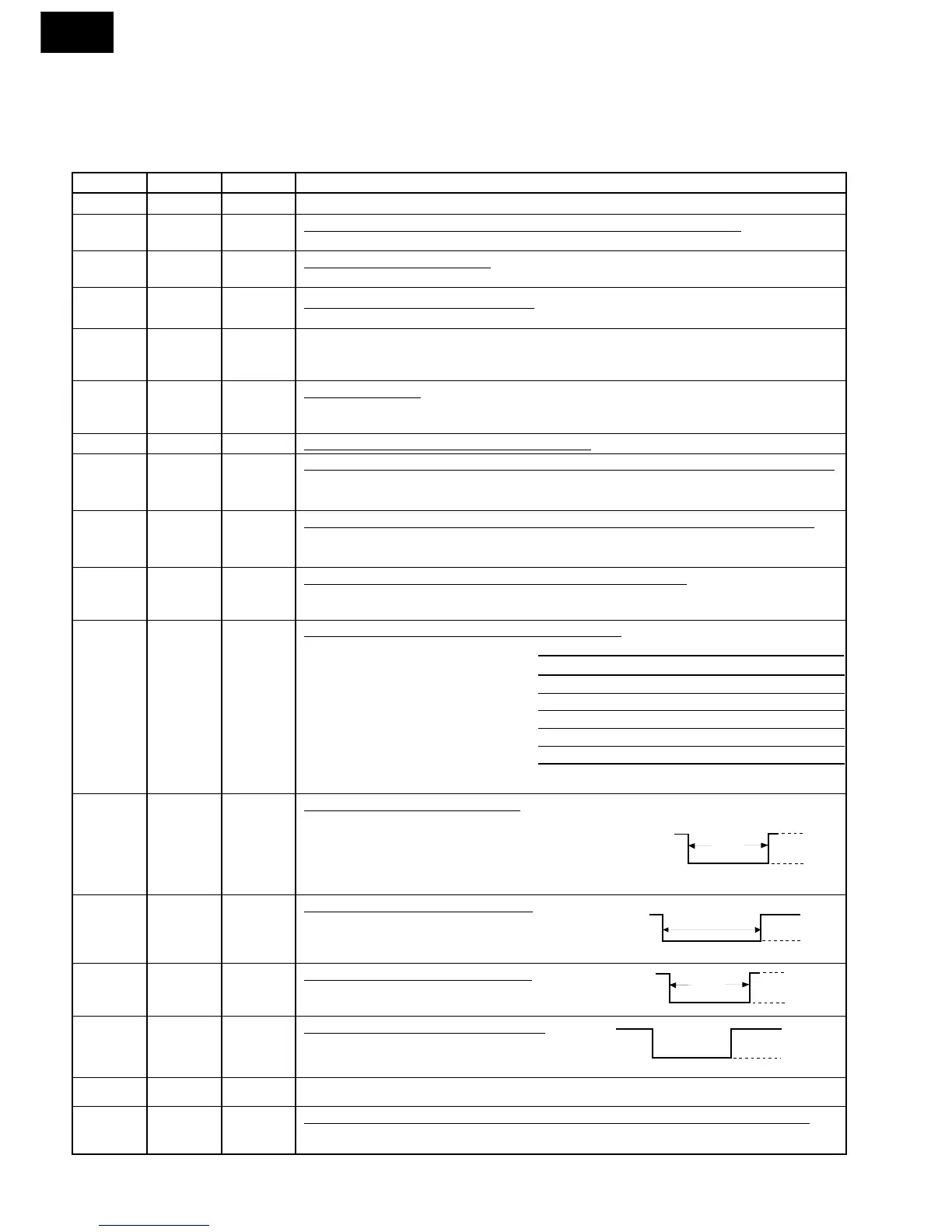
DESCRIPTION OF LSI
LSI(IZA589DR):
The I/O signals of the LSI(IZA589DR) are detailed in the following table.
Pin No. Signal I/O Description
VARI MODE ON TIME OFF TIME
HIGH (100% power) 32 sec. 0 sec.
MED HIGH (approx. 70% power) 24 sec. 8 sec.
MED (approx. 50% power) 18 sec. 14sec.
MED LOW (approx. 30% power) 12 sec. 20 sec.
LOW (approx. 10% power) 6 sec. 26 sec.
ON
OFF
During
cooking
L
GND
H.
(Convection)