R-9H56
30
CAUTION:
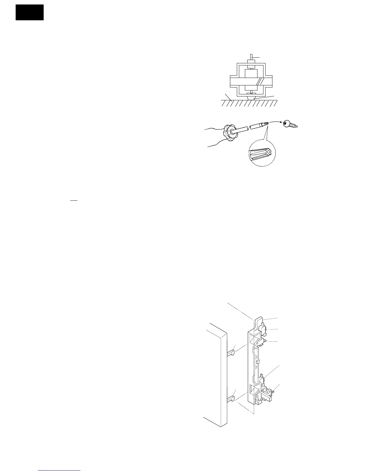
* Do not hit the fan blade strongly when installed
because the bracket may be transformed.
* Make sure that the fan blade rotates smooth after
installed.
* Make sure that the axis of the shaft is not slanted.
3. Install the fan duct to the air guide.
4. Install the chassis support to the oven cavity with three
(3) screws.
Shaft
Table
Center of
bracket
5. Connect the wire leads to the fan motor and the thermal
cut-out, referring to the pictorial diagram.
Refer to chapter “Test Procedure” and Adjustment procedure.
STOP SWITCH, UPPER LATCH SWITCH, LOWER LATCH SWITCH AND MONITOR SWITCH A
DJUSTMENT
If those switches do not operate properly due to a
misadjustment, the following adjustment should be made.
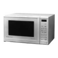
1. Loosen the two (2) screws holding the latch hook to the
flange on the oven front face.
2. With the door closed, adjust the latch hook by moving it
back and forth and then adjust the latch hook by moving
it back and forth. In and out play of the door allowed by
the latch hook should be less than 0.5 mm.
3. Secure the screws with washers firmly.
4. Now, make sure of the upper and lower latch switches
operations. If these latch switches are not activated with
the door closed, loose the screws holding the latch hook
to the oven cavity front flange and adjust the latch hook
position.
After the adjustment, make sure of the following:
1. The in and out play of the door remains less than 0.5 mm
at latched position.
2. The upper and lower latch switches interrupt the circuit
before the door can be opened.
3. The monitor switch contacts close when the door is
opened.
4. Re-install the outer case and check for microwave leakage
around the door with an approved microwave survey
meter. (Refer to Microwave Measurement Procedure.)
Figure C-1. Latch Switches Adjustment
STOP SWITCH, UPPER LATCH SWITCH, LOWER LATCH SWITCH AND MONITOR SWITCH
REMOVAL
1. CARRY OUT 3D CHECKS.
2. Remove control panel assembly, refer to “Control Panel
Removal”.
3. Discharge high voltage capacitor.
4. Disconnect wire leads from each of the switches.
5. Remove two (2) screws holding latch hook to oven
flange.
6. Remove latch hook assembly from oven flange.
7. Push downward on the one (1) stopper tabs holding each
of the switches place.
8. Switches are free.
At this time latch lever will be free, do not lose it.
Re-install
1. Re-install latch lever and each switch in its place, refer to
Figure C-1.
2. Re-connect the wire leads to each switches and fuse
holder.
Refer to the pictorial diagram.
3. Secure the latch hook (with two (2) mounting screws) to
the oven flange.
4. Make sure that monitor switch is operating properly.
CORD HOLDER REMOVAL
1. Remove the one (1) special screw holding the cord
holder to the rear cabinet, using the special driver
LHSTIX DLR4-100T.
2. Now, the cord holder is free.
NOTE: When securing or loosening the special screw,
LHSTIX DLR4-100T type screw driver should be
used.