RCD1200M
10 – 3
3. Discharge two high voltage capacitors.
4. Remove the two (2) screws holding the capacitor unit angle to the
intake duct assembly or the exhaust duct assembly.
5. Remove one (1) screw holding the capacitor band to capacitor unit
angle.
6. Remove one (1) screw holding ground side terminals of high volt-
age rectifier assembly to the capacitor band.
7. Remove the capacitor band from the high voltage capacitor.
8. Disconnect all wire leads from the high voltage capacitor.
9. Now, the capacitor (1) or (2) and the high voltage rectifier assembly
are free.
CAUTION: 1) DISCHARGE THE TWO HIGH VOLTAGE CAPACITOR
BEFORE TOUCHING ANY OVEN COMPONENTS OR
WIRING.
2) DO NOT REPLACE ONLY THE HIGH VOLTAGE REC-
TIFIER. IF IT IS DEFECTIVE, REPLACE THE HIGH
VOLTAGE RECTIFIER ASSEMBLY.
3) WHEN REPLACING THE HIGH VOLTAGE RECTIFIER
ASSEMBLY AND THE HIGH VOLTAGE CAPACITOR,
THE GROUND SIDE TERMINAL OF THE HIGH VOLT-
AGE RECTIFIER MUST BE SECURED FIRMLY WITH
A GROUNDING SCREW.
[7] POWER SUPPLY CORD REPLACEMENT
1. REMOVAL
1. Disconnect the power supply cord and then remove the outer case
and the rear cover referring to “OUTER CASE AND REAR COVER
REMOVAL”.
2. Open the oven door and block it open.
3. Discharge the two high voltage capacitors.
4. Remove the one (1) screw holding the grounding wire of the power
supply cord to the oven cavity.
5. Disconnect the wire leads of the power supply cord from the noise
filter.
6. Remove the one (1) screw holding the power supply cord angle to
the capacitor unit angle.
7. Remove the power supply cord angle with the power supply cord
from the capacitor unit angle.
8. Nip the cord bushing with the bushing pliers and release it from the
power supply cord angle.
9. Remove the cord bushing with the power supply cord from the
power supply cord angle.
10.Remove the cord bushing from the power supply cord.
11.Now, the power supply cord is free.
2. INSTALLATION
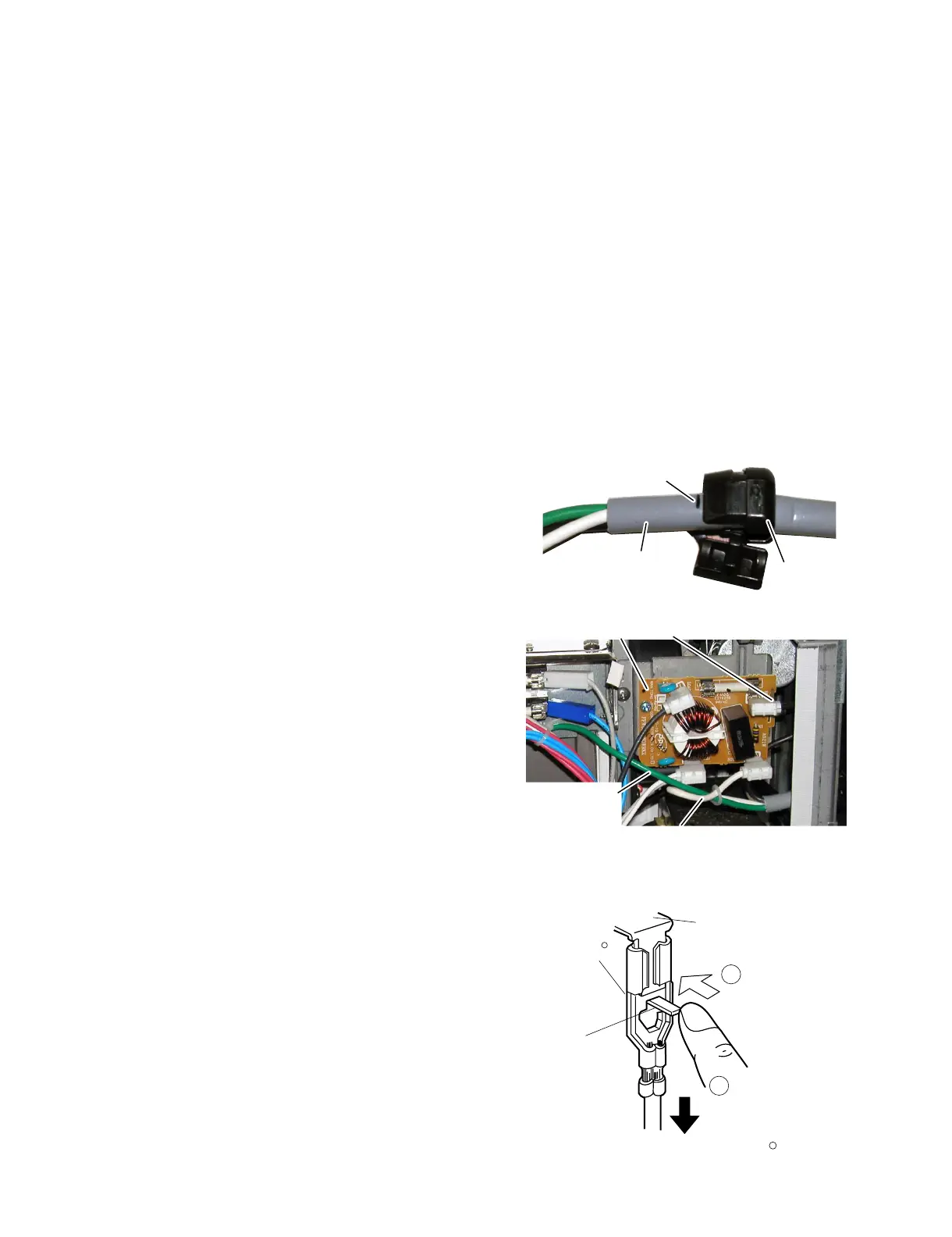
1. Install the cord bushing to the power supply cord so that the small
line on the power supply cord surface comes to the end of the cord
bushing as shown in the.Figure C-2.
2. Install the cord bushing (with the power supply cord) into the hole of
the power supply cord angle with the bushing pliers.
3. Reinstall the power supply cord angle to the capacitor unit angle
with the one (1) screw.
4. Install the grounding wire of the power supply cord to the oven cav-
ity with the one (1) screw.
5. Connect the black wire lead of the power supply cord to the source
side upper terminal of the noise filter.
6. Connect the white wire lead of the power supply cord to the source
side lower terminal of the noise filter.
7. Reinstall the rear cover, the magnetron exhaust cover and the
outer case cabinet and check that the oven is operating properly.
Figure C-2(a) Cord bushing position
Figure C-2(b) Wiring to the noise filter
[8] HOW TO RELEASE THE POSITIVE LOCK CONNECTOR.
1. Disconnect the power supply cord and then remove outer case
and rear cover, referring to “OUTER CASE AND REAR COVER
REMOVAL”.
2. Open the door and block it open.
3. Discharge high voltage capacitor.
4. Push the lever of positive lock® connector, pull down the connec-
tor from terminal.
5. Now, the connector is free.
CAUTION: THE POSITIVE LOCKR TERMINAL CAN NOT BE
REMOVED BYJUST PULLING ON IT. THE LOCK
LEVER MUST BE RELEASED TO REMOVE THE CON-
NECTOR FROM THE TERMINAL.
Cord bushing
Small line
Power supply cord
Grounding wire of
power supply cord
Black wire lead of power supply cord
White wire lead of power supply cord
Noise filter
Terminal
Push
Pull down
1
Lever
Positive lock
R
connector
Figure C-3. How to release the positive lock
R
connector
2