Do you have a question about the Sharp R-CD1200M and is the answer not in the manual?
Steps to take before performing any service on the oven.
Procedures to follow before commencing any service work.
Steps after testing is finished and before reassembly.
Final steps after the repair is completed and before final checks.
Specifies the limits and conditions for microwave leakage measurement.
Steps to prepare the oven and equipment for leakage testing.
Detailed procedure for performing the microwave leakage test.
Specific warnings about high-voltage parts and potential hazards.
Technical specifications of the microwave oven.
Guidelines for proper grounding of the appliance.
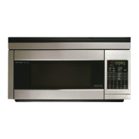
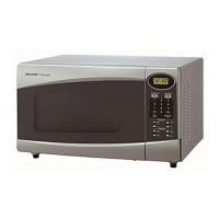
Labeled diagram of the oven's external and internal components.
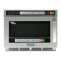
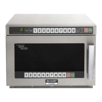
Labeled diagram of the control panel buttons and layout.
Explains the sequence of operations for different oven conditions.
Details the operational sequence when cooking is in progress.
Explains how variable power levels affect cooking time.
Schematic diagram of the oven's electrical circuits during cooking.
Explains the function of temperature fuses for magnetron protection.
Details the function of the oven temperature fuse for fire prevention.
Explains the function of magnetron thermistors for overheat detection.
Explains the function and operation of the exhaust motor.
Describes the function of antenna motors in radiating microwaves.
Details the function of the 12A fuses in protecting against shorts and overloads.
Lists error codes, history display, and corresponding error descriptions.
Procedure to test the magnetron for proper function and continuity.
Method to measure microwave power output using a water temperature rise test.
Procedure to test the power transformer's primary and secondary coils.
Steps to test the high voltage rectifier using an ohmmeter.
Procedure to test the asymmetric rectifier for proper forward/reverse bias.
Procedure to test the high voltage capacitor for shorts or opens.
Test procedure for secondary interlock switches.
Test procedure for the primary interlock system.
Test procedure for the door sensing switch.
Test procedure for the primary interlock relay.
Procedure to test monitor switches for correct operation.
Procedure for testing and replacing a blown monitor fuse.
Procedure to test the 12A fuses for continuity.
Procedure to test magnetron and oven temperature fuses.
Procedure to test magnetron thermistors for resistance.
Procedure to test the exhaust thermistor using a special function.
Procedure to test the noise filter for shorts or opens.
Procedure to test the key unit for proper response and connectivity.
Procedure to test the control unit for faults based on symptoms.
Procedure to test the power unit's output voltage and fuses.
Procedure to test the relay unit's fuse and relay contacts.
Information on diagnosing antenna sensor faults based on error codes.
Information on diagnosing microwave sensor faults based on error codes.
Explains special functions for checking part usage time and settings.
Procedures for checking, clearing, and setting component usage data.
Procedure to check recent error history codes stored in memory.
Procedure to check the exhaust thermistor's function using SF-6.
Procedure to check control unit installation and display model/date info.
Safety precautions for handling sensitive electronic components like CMOS LSI.
Procedures for servicing PWBs with oven power or external power.
Lists essential tools required for servicing printed wiring boards.
Additional precautions to follow when servicing printed wiring boards.
Information on identifying and using lead-free solder on PCBs.
Guidelines for using lead-free wire solder for repairs.
Techniques and precautions for soldering with lead-free solder.
General warnings related to high voltage and microwave energy exposure.
Specific precautions to take before and during wiring operations.
Step-by-step procedure for removing the outer case and rear cover.
Procedure for removing the power transformers.
Procedure for removing the magnetrons.
Procedures for removing and reinstalling the magnetron thermistor assembly.
Procedure for removing HV capacitors and rectifier assemblies.
Detailed steps for removing and installing the power supply cord.
Instructions on how to safely disconnect positive lock connectors.
Procedure for removing the exhaust fan.
Procedure for removing the fan motors.
Procedures for removing upper and lower antenna motors.
Procedure for removing the power unit.
Procedure for removing the relay unit.
Procedures for removing the control panel and control unit.
Steps for removing door sensing, secondary interlock, and monitor switches.
Steps for reinstalling door sensing, secondary interlock, and monitor switches.
Procedure for adjusting door sensing, interlock, and monitor switches.
Steps for removing the oven door assembly.
Steps for reinstalling the oven door assembly.
Procedure for adjusting the door alignment and switch activation.
Procedure for removing the choke cover from the door.
Procedure for removing the door panel from the door frame.
Procedure for removing the key unit from the door assembly.
Procedure for removing the switch unit from the door assembly.
Procedure for removing the front door glass.
Procedure for removing door handle, lever, and cover.
Procedure for removing upper and lower latch heads.
Procedure for removing the door case from the door frame.
Important note on positioning harness and pipe during reassembly.
Visual representation of component locations and wiring.
Shows wiring on the left side of the oven.
Shows wiring on the top of the oven.
Diagram illustrating the wiring of high voltage components.
Shows the wiring connections for the control unit.
Image and wiring details of the switching power supply.
Image and wiring details of the relay unit.
Instructions on how to correctly order replacement parts.
Section listing parts for the oven assembly.
Section listing parts for the door and control panel.
| Brand | Sharp |
|---|---|
| Model | R-CD1200M |
| Category | Microwave Oven |
| Language | English |