EasyManua.ls Logo

Sharp SB-29S User Manual

Sharp SB-29S
19 pages
To Next Page IconTo Next Page
Page #1 background imageLoading...
Page #1 background image
SHARP SERVICE MANUAL
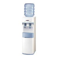
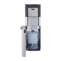
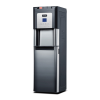
HOT & COLD WATER DISPENSER
MODEL SB-29
SB-29S
In the interests of user-safety (Required by safety
regulations in some countries) the set should be restore
to its original condition and only parts identical to those
specied should be used.
SHARP CORPORATION
TABLE OF CONTENTS
PARTS IDENTIFICATION AND SPECIFIC INFORMATION ...................................................
CAUTIONS FOR USE .............................................................................................................
IMPORTANT SAFETY INSTRUCTIONS ................................................................................
WIRING DIAGRAM AND CIRCUIT DIAGRAM .......................................................................
COOLING SYSTEM DIAGRAM AND HOT SYSTEM DIAGRAM ...........................................
COMPONENT REPLACEMENT PROCEDURE .....................................................................
TROUBLESHOOTING ............................................................................................................
SERVICE PARTS LIST ...........................................................................................................
Page
2
3
3
4
5
6 - 13
14
15 - 19

Questions and Answers:

Sharp SB-29S Specifications

General IconGeneral
BrandSharp
ModelSB-29S
CategoryWater Dispenser
LanguageEnglish

Summary

PARTS IDENTIFICATION

SPECIFIC INFORMATION

CAUTIONS FOR USE

IMPORTANT SAFETY INSTRUCTIONS

WIRING DIAGRAM

CIRCUIT DIAGRAM

COOLING SYSTEM DIAGRAM

HOT WATER SYSTEM DIAGRAM

COMPONENT REPLACEMENT PROCEDURE

REMOVE OF PTC RELAY

Step-by-step guide for safely removing the PTC relay.

REMOVE OF THERMO MOTOR

Procedure for disconnecting and removing the thermo motor.

REMOVE OF POWER CORD ASS'Y

Steps to safely disconnect and remove the power cord assembly.

REMOVE OF THERMOSTAT

Guide to removing the thermostat unit from its mounting.

REMOVE OF FUSE ASS'Y

Instructions for safely removing the fuse assembly.

REMOVE OF PANEL B-A AND FAUCET ASS'Y

Procedure for disassembling panels and faucet units.

REMOVE OF TEMP. FUSE ASS'Y

Steps to remove the temperature fuse assembly.

REMOVE OF THERMOSTAT (42°C, 93°C)

Details for removing specific temperature thermostats.

REMOVE OF PCB HOT DISPLAY AND PCB COOL DISPLAY

Guide for removing the hot and cool display circuit boards.

REMOVE OF FAUCET CONNECTOR AND TANK CONNECTOR

Steps to detach faucet and tank connectors.

REMOVE OF SIDE PLATE L-R

Procedure for removing left and right side panels.

REMOVE OF SPACE TANK

Instructions for removing the internal space tank.

REMOVE OF HEATER TANK ASS'Y

Steps to remove the heater tank assembly.

REMOVE OF HEATER SET ASS'Y

Procedure for removing the heater set assembly.

REMOVE OF FILTER DRIERS

Steps for removing the filter driers unit.

REMOVE OF COMPRESSOR

Guide for safely removing the compressor unit.

TROUBLESHOOTING

SERVICE PARTS LIST

Related product manuals