Do you have a question about the Sharp SMC1585BS and is the answer not in the manual?
Essential safety measures before and during microwave oven servicing.
Critical safety steps to perform prior to servicing the oven.
Post-repair procedures and safety checks for the oven.
Procedure for testing microwave leakage with the oven assembled.
Procedure for testing microwave leakage with the outer case removed.
Description of the safety feature that detects fire during cooking.
Step-by-step guide for diagnosing and resolving oven problems.
Procedure to test the magnetron for continuity and shorts.
Method to measure microwave power output using a water test.
Testing the power transformer for coil continuity and resistance.
Procedure to test the high voltage rectifier assembly.
How to test the high voltage capacitor for shorts or opens.
Testing secondary and primary interlock switches for proper operation.
Testing the primary interlock relay (RY2) contacts.
Testing the monitor switch for proper operation.
Steps to take when the monitor fuse has blown.
Testing the magnetron temperature fuse.
Testing the convection thermal cut-out.
Procedures to test the heating element resistance and insulation.
Testing the thermistor resistance at different temperatures.
Testing the damper motor for operation and voltage.
Testing the damper switch for continuity.
Procedures for testing the key unit and control unit of the panel.
Testing the functionality of the touch control panel's key unit.
Checking the operational voltage of various relays.
Steps to check and repair foil patterns on the PWB acting as fuses.
Testing the absolute humidity sensor for proper operation.
Methods to test the absolute humidity sensor and control unit.
Steps for servicing the touch control panel using oven or external power.
Steps to remove the control panel assembly and control unit.
| Style | counter top |
|---|---|
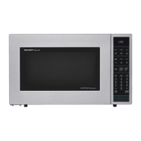
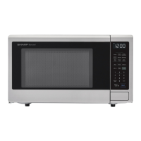
| Color | stainless steel |
| Total Capacity | 1.5 cu. ft. |
| Control Options | reheat, popcorn, +60 sec, auto broil, auto roast, auto bake, auto defrost, preheat, convect, broil, low & high mix |
| Convection | yes |
| Power Levels | 10 |
| Sensor Cooking | yes |
| Quick Start | no |
| Defrost | by weight or by time |
| Control Type | touch control |
| Timer | no |
| Interior Light | yes |
| Microwave Power | 900 watts |
| Electrical Requirements | ac 120v/60hz |
| Voltage | 120 volts |
| Current | 15 |
| Depth | 19 inch |
|---|---|
| Height | 14 9/10 inch |
| Width | 24 7/10 inch |
| Net Weight | 60 lbs. |