13
is channelled through the cavity to remove steam and vapors
given off from the heating foods. It is then exhausted at the top of
the oven cavity into a condensation compartment.
Convection Cooking:
Damper is in the closed position, so that no hot air will be
allowed to leak out the oven cavity.
Damper Operation
1. When power supply cord is plugged in:
1-1. When power supply cord is plugged in, a signal is
sensed in the control unit, and operates shut-off relay
(RY4).
1-2. Contacts of shut-off relay (RY4) close, the damper
motor is energized, opening the damper door.
1-3. When the damper is moved to the open position by the
damper cam the damper switch is closed (ON position).
1-4. The signal from damper switch is re-sensed in the
control unit and shut-off relay (RY4) is turned off.
1-5. The 120 volts A.C. to the damper motor is removed
and the motor turns off.
2. When oven is microwave cooking:
Damper is in the open position.
3. When oven is convection cooking:
3-1. Damper motor is energized by touching the convection,
temperature and START pads.
3-2. When damper is in the closed position (damper switch
is OFF), its signal is sensed by the control unit,
and
shut-off relay (RY4) is de-energized.
3-3. The damper is held in the closed position during the
convection cooking operation.
3-4. At the end of the convection cooking, shut-off relay
(RY4) is energized, and the damper is returned to the
open position.
NOTE: If the damper door is not in the proper position,
closed during convection or open during microwave,
the control unit will stop oven operation after 1
minute.
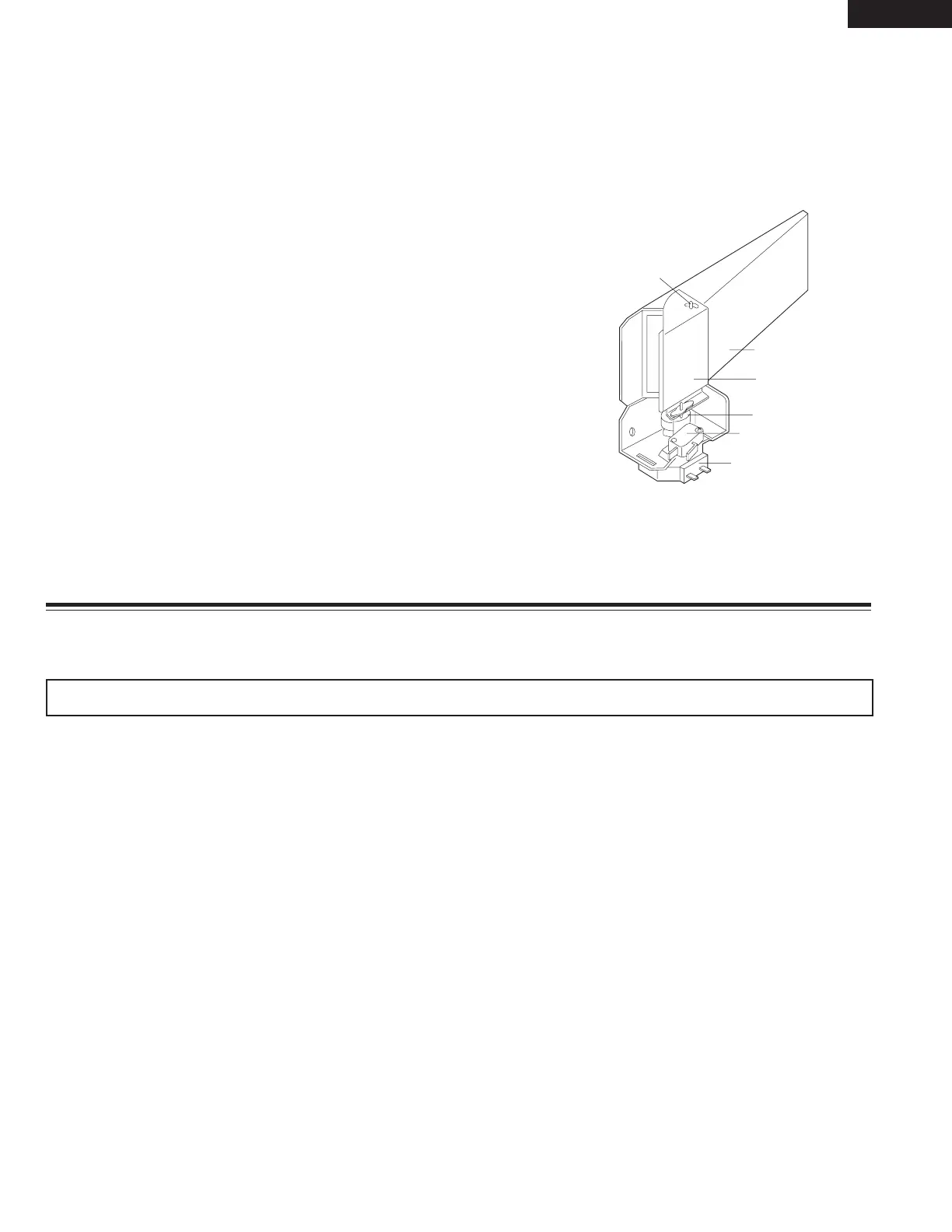
Figure D-2. Damper Mechanism
DAMPER DUCT
DAMPER
DAMPER CAM
DAMPER MOTOR
DAMPER SWITCH
DAMPER SHAFT
TROUBLESHOOTING GUIDE
Never touch any part in the circuit with your hand or an uninsulated tool while the power supply is connected.
When troubleshooting the microwave oven, it is helpful to follow the Sequence of Operation in performing the checks. Many
of the possible causes of trouble will require that a specific test be performed. These tests are given a procedure letter which
will be found in the "Test Procedure "section.
IMPORTANT: If the oven becomes inoperative because of a blown monitor fuse, check the monitor switch, relay (RY1) primary
interlock relay (RY2), door sensing switch and secondary interlock switch before replacing the monitor fuse. If the
monitor fuse is replaced, the monitor switch must also be replaced. Use part FFS-BA021WRK0 as an assembly.
IMPORTANT: Whenever troubleshooting is performed with the power supply cord disconnected. It may in, some cases, be
necessary to connect the power supply cord after the outer case has been removed, in this event,
1. Disconnect the power supply cord, and then remove outer case.
2. Open the door and block it open.
3. Discharge high voltage capacitor.
4. Disconnect the leads to the primary of the power transformer.
5. Ensure that the leads remain isolated from other components and oven chassis by using insulation tape.
6. After that procedure, reconnect the power supply cord.
When the testing is completed
1. Disconnect the power supply cord, and then remove outer case.
2. Open the door and block it open.
3. Discharge high voltage capacitor.
4. Reconnect all leads removed from components during testing.
5. Reinstall the outer case (cabinet).
6. Reconnect the power supply cord after the outer case is installed.
7. Run the oven and check all functions.
SMC1585BSA
SMC1585BBA
SMC1585BWA