36
POWER SUPPLY CORD REPLACEMENT
Removal
1.
Disconnect the power supply cord, and remove outer case.
2. Open the door and block it open.
3. Discharge high voltage capacitor.
4. Remove the single (1) screw holding the green wire to the
base cabinet.
5. Disconnect the leads of the power supply cord from the
noise filter, referring to the Figure C-3(a).
6. Release the moulding cord stopper of the power supply
cord from the square hole of the rear cabinet, referring to the
Figure C-3(b).
7. Now, the power supply cord is free.
Re-install
1. Insert the moulding cord stopper of power supply cord into
the square hole of the rear cabinet, referring to the Figure
C-3 (b).
2. Install the earth wire lead of power supply cord to the base
cabinet with one (1) screw and tight the screw.
3. Connect the gray wire leads of power supply cord to the
noise filter correctly, referring to the Pictorial Diagram.
4. Re-install outer case and check that the oven is operating
properly.
to the fan duct.
21.Now, the fan motor is free.
INSTALLATION
1. Install the fan motor to the fan duct with the two (2) screws
and nuts.
2. Install the fan blade to the fan motor shaft according the
following procedure.
3. Hold the center of the bracket which supports the shaft of
the fan motor on the flat table.
4. Apply the screw lock tight into the hole (for shaft) of the fan
blade.
5. Install the fan blade to the shaft of fan motor by pushing the
fan
blade with a small, light weight, ball peen hammer or
rubber mallet.
CAUTION:
* Do not hit the fan blade strongly when installed because
the bracket may be disfigured.
* Make sure that the fan blade rotates smooth after
installation.
* Make sure that the axis of the shaft is not slanted.
6. Reset the fan duct assembly to its place.
7. Install the tabs of fan duct to the rear cabinet and air guide.
8. Install the magnetron air guide with the one (1) screw.
9. Reinstall the main harness and thermistor harness to each
hole of the fan duct.
10.Reinstall the chassis support to the control panel back
plate, waveguide and rear cabinet with the three (3) screws.
11.Re-connect the wire leads to the fan motor, referring to the
pictorial diagram.
12.Re-install the fan motor grounding wire to the air guide
(Right) with one (1) screw.
Rear View
Side View
Gap
Rotor
Bracket
Stator
Groove joint pliers
Coil
Shaft
Axis
Stator
Rotor
These are the positions
that should be pinched
with pliers
Shaft
Table
Center of
bracket
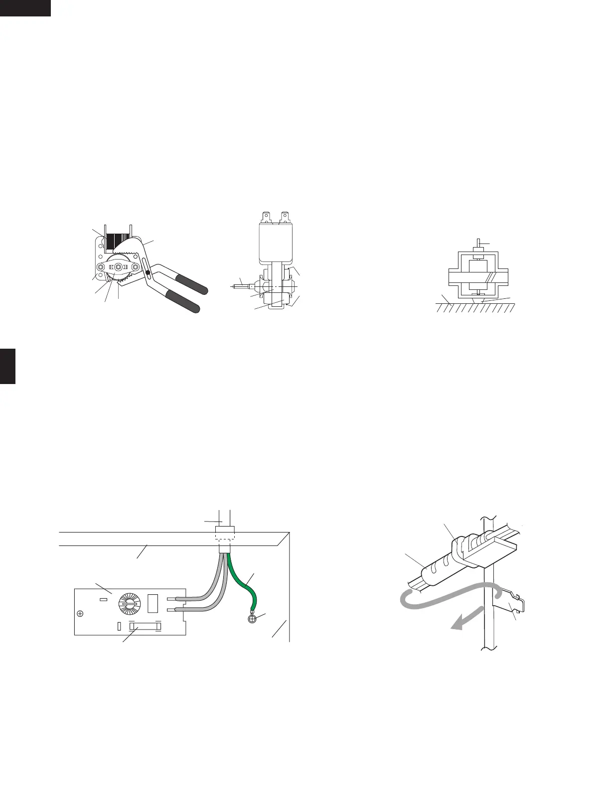
Figure C-3(a) Power Supply Cord Replacement
Figure C-3(a) Power Supply Cord Replacement
RED
WHT
Power Supply Cord
Screw
*
Gray Wire
*
Connect the wire lead which has black case to
the terminal "L" of the noise filter
Gray Wire
Base Cabinet
Fuse
Noise Filter
Rear cabinet
L
N
Green Wire
Power Supply
Cord
Square
Hole
Moulding
Cord Stopper
DOOR SENSING SWITCH/SECONDARY INTERLOCK SWITCH AND MONITOR SWITCH REMOVAL
1. Disconnect the power supply cord and then remove outer
case.
2. Open the oven door and block it open.
3. Discharge high voltage capacitor.
4. Remove the control panel assembly, refer to "Control Panel
Removal".
SMC1585BSA
SMC1585BBA
SMC1585BWA