18
TEST PROCEDURES
PROCEDURE
LETTER
COMPONENT TEST
4. A continuity check across the temperature fuse terminals should indicate a closed circuit unless the
temperature of the magnetron reaches approximately 302˚F(150˚C). An open temperature fuse indicates
overheating of the magnetron. Check for restricted air flow to the magnetron, especially the cooling duct
and cooling fan.
5. Reconnect all leads removed from components during testing.
6. Reinstall the outer case (cabinet).
7. Reconnect the power supply cord after the outer case is installed.
8. Run the oven and check all functions.
CAUTION: IF THE TEMPERATURE FUSE INDICATES AN OPEN CIRCUIT AT ROOM TEMPERATURE,
REPLACE TEMPERATURE FUSE.
1. Disconnect the power supply cord, and then remove outer case.
2. Open the door and block it open.
3. Discharge high voltage capacitor.
4. A continuity check across the thermal cut-out terminals should indicate a closed circuit unless the
temperature of the thermal cut-out reaches approximately 302˚F(150˚C). The thermal cut-out resets
automatically at approximately 266˚F(130˚C). If thermal cut-out has opened under normal condition,
replace the same item as in the parts list.
An open thermal cut-out indicates overheating of the heater unit. Check for restricted air flow to the heater
unit through the vent holes of the oven cavity, especially the heater duct and convection fan.
5. Reconnect all leads removed from components during testing.
6. Reinstall the outer case (cabinet).
7. Reconnect the power supply cord after the outer case is installed.
8. Run the oven and check all functions.
CAUTION: IF THE THERMAL CUT-OUT INDICATES AN OPEN CIRCUIT AT ROOM TEMPERATURE,
REPLACE THERMAL CUT-OUT.
K HEATING ELEMENT TEST
1. Disconnect the power supply cord, and then remove outer case.
2. Open the door and block it open.
3. Discharge high voltage capacitor.
4. Make sure the heating element is fully cooled and test as follows;
a. Disconnect wire leads from the heating element and measure the resistance with an ohmmeter. On the
R x 1 scale, the resistance between the heating element terminals should be approximately 10.2Ω.
b. Disconnect wire leads from the heating element and measure the insulation resistance with 500V -
100MΩ insulation resistance meter. The insulation resistance between heating element terminal and
cavity should be more than 0.5MΩ.
5. If the meter does not indicate above resistance, replace the thermistor
6. Reconnect all leads removed from components during testing.
7. Reinstall the outer case (cabinet).
8. Reconnect the power supply cord after the outer case is installed.
9. Run the oven and check all functions.
J CONV. THERMAL CUT-OUT TEST
1. Disconnect the power supply cord, and then remove outer case.
2. Open the door and block it open.
3. Discharge high voltage capacitor.
4. Disconnect connector-E from the control unit. Measure the resistance of the thermistor with an ohmmeter.
Connect the ohmmeter leads to Pin No’s E-3 and E-4.
Room Temperature Resistance
68˚F(20˚C) - 86˚F(30˚C) Approx. 350kΩ - 155KΩ
5. If the meter does not indicate above resistance, replace the thermistor.
6. Reconnect all leads removed from components during testing.
7. Reinstall the outer case (cabinet).
L THERMISTOR TEST
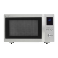
SMC1585BSA
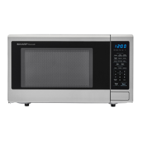
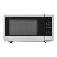
SMC1585BBA
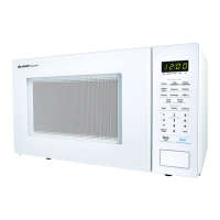
SMC1585BWA