21
TEST PROCEDURES
PROCEDURE
LETTER
COMPONENT TEST
a) When touching the pads, a certain group of pads do not produce a signal.
b) When touching the pads, no pads produce a signal.
2-2 In connection with indicators
a) At a certain digit, all or some segments do not light up.
b) At a certain digit, brightness is low.
c) Only one indicator does not light.
d) The corresponding segments of all digits do not light up; or they continue to light up.
e) Wrong figure appears.
f ) A certain group of indicators do not light up.
g) The figure of all digits flicker.
2-3 Other possible problems caused by defective control unit.
a) Buzzer does not sound or continues to sound.
b) Clock does not operate properly.
c) Cooking is not possible.
When testing is completed,
1) Disconnect the power supply cord, and then remove outer case.
2) Open the door and block it open.
3) Discharge high voltage capacitor.
4) Reconnect all leads removed from components during testing.
5) Re-install the outer case (cabinet).
6) Reconnect the power supply cord after the outer case is installed.
7) Run the oven and check all functions.
R KEY UNIT TEST
1. Disconnect the power supply cord, and then remove outer case.
2. Open the door and block it open.
3. Discharge high voltage capacitor.
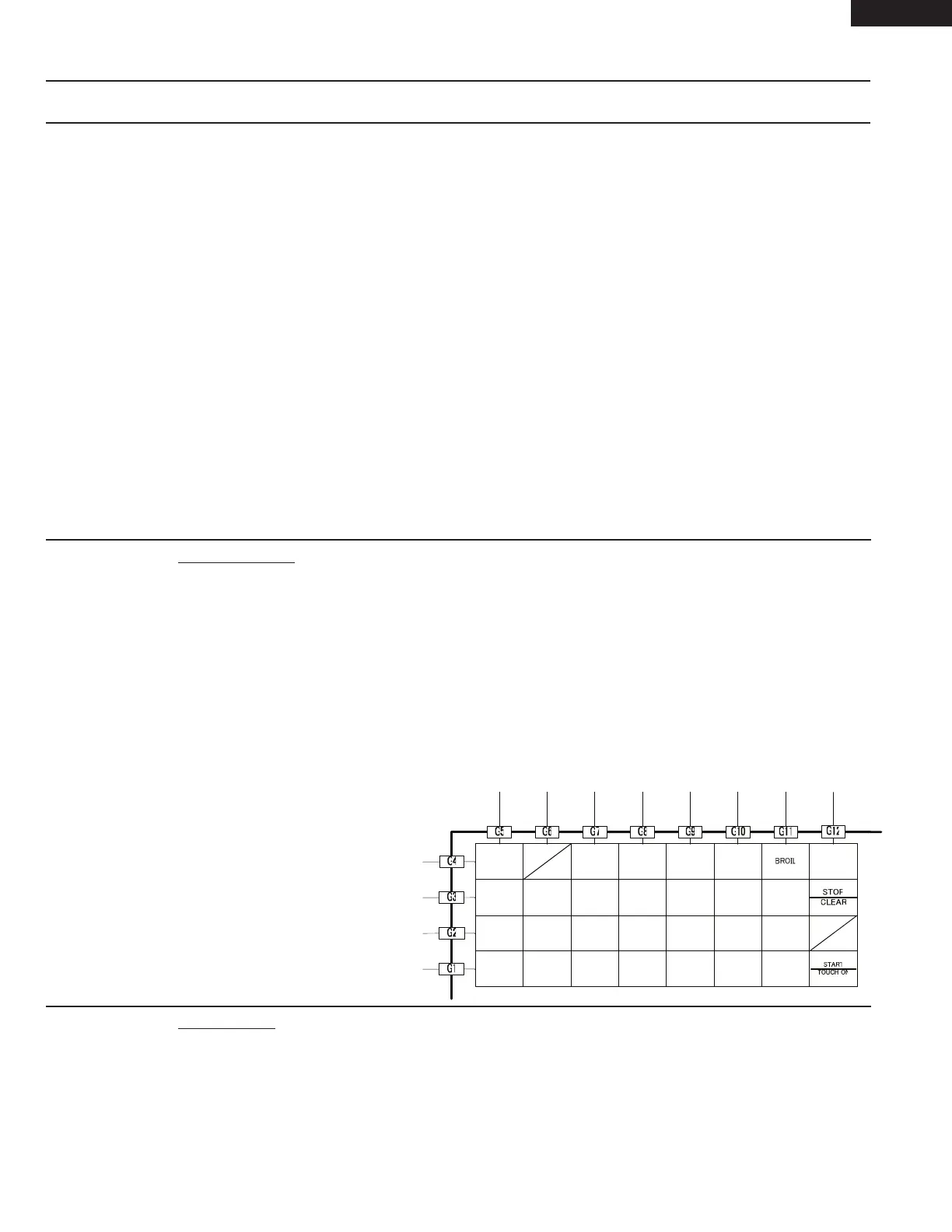
4. If the display fails to clear when the STOP/CLEAR pad is depressed, first verify the flat ribbon cable is
making good contact, verify that the door sensing switch (stop switch) operates properly; that is the
contacts are closed when the door is closed and open when the door is open. If the door sensing switch
(stop switch) is good, disconnect the flat ribbon cable that connects the key unit to the control unit and make
sure the door sensing switch is closed (either close the door or short the door sensing switch connecter).
Use the Key unit matrix indicated on the control panel schematic and place a jumper wire between the pins
that correspond to the STOP/CLEAR pad making momentary contact. If the control unit responds by
clearing with a beep the key unit is faulty and must be replaced. If the control unit does not respond, it is
faulty and must be replaced. If a specific pad does not respond, the above method may be used (after
clearing the control unit) to
determine if the
control unit or key
pad is at fault.
5. Reconnect all leads removed from
components during testing.
6. Re-install the outer case (cabinet).
7. Reconnect the power supply cord
after the outer case is installed.
8. Run the oven and check all
functions.
S RELAY TEST
1. Disconnect the power supply cord, and then remove outer case.
2. Open the door and block it open.
3. Discharge high voltage capacitor.
4. Disconnect the leads to the primary of the power transformer.
5. Ensure that these leads remain isolated from other components and oven chassis by using insulation tape.
6. After that procedure, re-connect the power supply cord.
7. Remove the outer case and check voltage between Pin Nos. 7 and 9 of the 9 pin connector (A) on the
control unit with an A.C. voltmeter. The meter should indicate 120 volts, if not check oven circuit.
SENSOR
MENU
1
100F
2
150F
7
375F
8
400F
HIGH
MIX
AUTO
DEFROST
HELP/
SETTINGS
AUTO
BRKE
AUTO
BROIL
AUTO
ROAST
POWER
LEVEL
3
275F
6
350F
9
425F
CLOCK
4
300F
TIMER
0
450F
5
325F
+60 SEC
REHEAT
CONVECT
POPCORN
LOW
MIX
PREHEAT
SLOW
COOK
SMC1585BSA
SMC1585BBA
SMC1585BWA