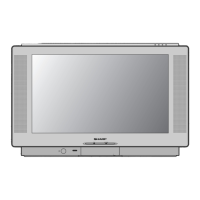
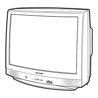
What to do if my Sharp SX76NF200 TV has no picture but noise or signal appear?
- SSandra MitchellAug 5, 2025
If your Sharp TV shows no picture but exhibits noise or signal, examine pin (12) of (SE), IC201, Q205, and their surrounding circuits.
What to do if my Sharp SX76NF200 TV has no picture but noise or signal appear?
If your Sharp TV shows no picture but exhibits noise or signal, examine pin (12) of (SE), IC201, Q205, and their surrounding circuits.
What to do if Sharp TV has no picture because of signal?
If your Sharp TV displays no picture and you suspect a signal issue, inspect IC4003 RGB output along with IC4003 and its related circuits.
What to do if my Sharp SX76NF200 has no picture because of noise?
If your Sharp TV has no picture and you suspect a noise issue, check R651 (Heater), the screen connection, and the circuits around T630 (FBT) and CRT.
What to do if Sharp TV has no picture because of signal or noise?
If your Sharp TV exhibits no picture with a signal or noise issue, check pin (3) of IC1801, IC1802, IC1803, and their peripheral circuits.
What to do if my Sharp SX76NF200 TV has no picture?
If your Sharp TV has no picture, you should check TU201 (tuner), SF201 and their surrounding components.
Lists the key features of the Colour Television.
Provides an overview of the manual's sections and their page numbers.
Safety precautions for servicing high voltage systems and the picture tube.
Precautions to minimize X-ray radiation exposure during servicing.
Safety checks to perform before returning the serviced TV to the user.
Instructions on how to enter the TV's service mode using different methods.
Explains how to navigate and use the service mode menu for adjustments.
Information on resetting the TV set and its effect on adjustment data.
Details on how to input and modify Non-Volatile Memory (NVM) data.
Adjustment points for vertical picture geometry settings.
Adjustment points for horizontal picture geometry settings.
Measurements related to tube characteristics, including cutoff settings.
Further measurements related to tube characteristics, including OSD shift.
Additional tube measurements, covering IBRM, CUT_DIS, CUT_GAIN, etc.
Adjustments for Brightness/Contrast Limit (BCL) and Sound/Video (SVM).
Adjustments related to the Extra High Tension (EHT) circuit.
Settings for IF AGC, Auto AGC, and Rotation adjustments.
Menu option for editing Non-Volatile Memory data.
Menu option to reset the TV set to default settings.
Adjustment procedure for the Picture Intermediate Frequency (PIF).
Adjustments for CRT cutoff and background settings.
Adjustment for white balance and background colour temperature.
Procedure to check the maximum beam current for the CRT.
Adjustment of sub-contrast for picture brightness and contrast.
Adjustment of sub-brightness for picture brightness levels.
Adjusting chroma settings for PAL colour system signals.
Adjusting chroma settings for NTSC colour system signals.
Adjustments for horizontal, vertical, and deflection loop parameters.
Adjustment for horizontal trapezoidal distortion.
Adjustment for horizontal cushion distortion.
Adjustment for the amplitude of picture corners.
Adjustment for the sixth harmonic of corner amplitude.
Adjustment for picture angle or tilt.
Adjustment for horizontal bow distortion.
Adjustment for S-correction, affecting vertical linearity.
Procedure for adjusting picture focus for sharpness.
Checks for the operation of protective circuits.
Checking the audio/video input and output signals.
Checking the contrast adjustment effect.
Checking the colour saturation adjustment effect.
Checking the brightness adjustment effect.
Checking the sharpness adjustment effect.
Checking the tint adjustment effect.
Checking the power save feature and LED indicator.
Checking the white temperature option.
Details on normal settings for picture modes.
Continued checks for video and audio function operations.
Checking colour system compatibility and proper operation.
Checking sound system compatibility and proper operation.
Checking the volume adjustment effect.
Checking the left-to-right balance effect.
Checking the bass adjustment effect.
Checking the treble adjustment effect.
Checking the super bass adjustment effect.
Checking headphone volume adjustment.
Procedures for checking operation in wide mode.
Checking wide mode changes (Panorama, Full, etc.).
Checking the vertical size effect in wide mode.
Checking the vertical scroll effect in wide mode.
Procedures for checking Twin Screen and Picture-in-Picture functions.
Checking twin screen picture quality and colour level.
Checking Picture-in-Picture picture quality, size, and position.
Checking Picture-in-Picture quality and position.
Checking live and freeze picture functions.
Checking multi-picture display via channel scan.
Procedures for checking TEXT mode functions.
Checking TEXT mode switching (Teletext, Mixed, Off).
Checking specific TEXT key functions (Half page, Hold, etc.).
Procedures for checking AV mode functions.
Checking AV mode switching (Standard, Movie, Music, News).
Flowchart for diagnosing and resolving "No Picture" issues.
Flowchart for diagnosing and resolving "No Sound" issues.
Flowchart for diagnosing combined "No Sound" and "No Picture" faults.
Flowchart for diagnosing and resolving "No Vertical Scan" problems.
Oscilloscope waveform at Pin 1, showing peak-to-peak voltage.
Oscilloscope waveform at Pin 2, showing peak-to-peak voltage.
Oscilloscope waveform at Pin 3, showing peak-to-peak voltage.
Oscilloscope waveform at Pin 4, showing peak-to-peak voltage.
Oscilloscope waveform at Pin 5, showing peak-to-peak voltage.
Oscilloscope waveform at Pin 6, showing peak-to-peak voltage.
Oscilloscope waveform at Pin 7, showing peak-to-peak voltage.
Oscilloscope waveform at Pin 8, showing peak-to-peak voltage.
Oscilloscope waveform at Pin 9, showing peak-to-peak voltage.
Oscilloscope waveform at Pin 10, showing peak-to-peak voltage.
Oscilloscope waveform at Pin 11, showing peak-to-peak voltage.
Oscilloscope waveform at Pin 12, showing peak-to-peak voltage.
Oscilloscope waveform at Pin 13, showing peak-to-peak voltage.
Oscilloscope waveform at Pin 14, showing peak-to-peak voltage.
Oscilloscope waveform at Pin 15, showing peak-to-peak voltage.
Oscilloscope waveform at Pin 16, showing peak-to-peak voltage.
Oscilloscope waveform at Pin 17, showing peak-to-peak voltage.
Oscilloscope waveform at Pin 18, showing peak-to-peak voltage.
Oscilloscope waveform at Pin 19, showing peak-to-peak voltage.
Oscilloscope waveform at Pin 20, showing peak-to-peak voltage.
Oscilloscope waveform at Pin 21, showing peak-to-peak voltage.
Oscilloscope waveform at Pin 22, showing peak-to-peak voltage.
Oscilloscope waveform at Pin 23, showing peak-to-peak voltage.
Oscilloscope waveform at Pin 24, showing peak-to-peak voltage.
Oscilloscope waveform at Pin 25, showing peak-to-peak voltage.
Oscilloscope waveform at Pin 26, showing peak-to-peak voltage.
Oscilloscope waveform at Pin 27, showing peak-to-peak voltage.
Schematic diagram for the CRT unit board.
Schematic diagram for the Control unit board.
Block diagram illustrating the functional connections of the Main Unit PWB-A.
Continued block diagram for the Main Unit PWB-A.
Wiring diagram of the Power Unit board (PWB-B).
Section of PWB-A related to the EW Amplifier.
Section of PWB-A related to the Side Pin Buffer.
Section of PWB-A related to the Side Pin Output.
Schematic diagram for the LED Unit board (PWB-F).
Schematic diagram for the Key Unit board (PWB-H).
Important safety instructions related to AC plug and heat sinks.
Notice regarding the importance of replacing specific parts for safety.
Precautionary measure involving an isolating transformer for AC mains voltage.
General notes on units of resistance, wattage, and capacitors.
Conditions under which voltage measurements are performed.
Conditions for measuring waveforms using a generator and voltmeter.
Schematic diagram for the CRT Unit.
Part 1 of the schematic for the Main Unit PWB-A.
Wiring diagram for the LED Unit board (PWB-F).
Wiring diagram for the Key Unit board (PWB-H).
Wiring diagram for the Power Unit board (PWB-B).
Component layout diagram for the IP Unit (PWB-D), A side.
Component layout diagram for the IP Unit (PWB-D), B side.
Wiring diagram for the Control Unit board (PWB-E).
Wiring layout of the Main Unit PWB-A, showing component placement.
Wiring layout of the IP Unit PWB-D, B side.
Information on safety-related parts and general part replacement.
Instructions for ordering replacement parts correctly and promptly.
List of replacement tuner parts.
List of replacement integrated circuit parts.
List of replacement transistor parts.
List of printed wiring board assemblies, marked as non-replaceable.
List of replacement diode parts.
List of replacement packaged circuit parts.
List of replacement coil parts.
List of replacement capacitor parts.
Continuation of the list of replacement capacitor parts.
List of replacement resistor parts.
Continuation of the list of replacement resistor parts.
List of replacement balun parts.
List of miscellaneous replacement parts.
List of replacement diode parts.
List of replacement packaged circuit parts.
List of replacement coil parts.
List of replacement capacitor parts.
List of replacement resistor parts.
List of replacement balun parts.
List of miscellaneous replacement parts.
List of replacement transistor parts.
List of replacement diode parts.
List of replacement packaged circuit parts.
List of replacement capacitor parts.
List of replacement resistor parts.
List of replacement packaged circuit parts.
List of replacement coil parts.
List of replacement capacitor parts.
List of replacement resistor parts.
List of replacement balun parts.
List of miscellaneous replacement parts.
List of replacement diode parts.
List of replacement resistor parts.
List of replacement switch parts.
List of replacement balun parts.
Diagram showing the location of cabinet parts.