Vl-E39S
Vl-E39S
4
m4.
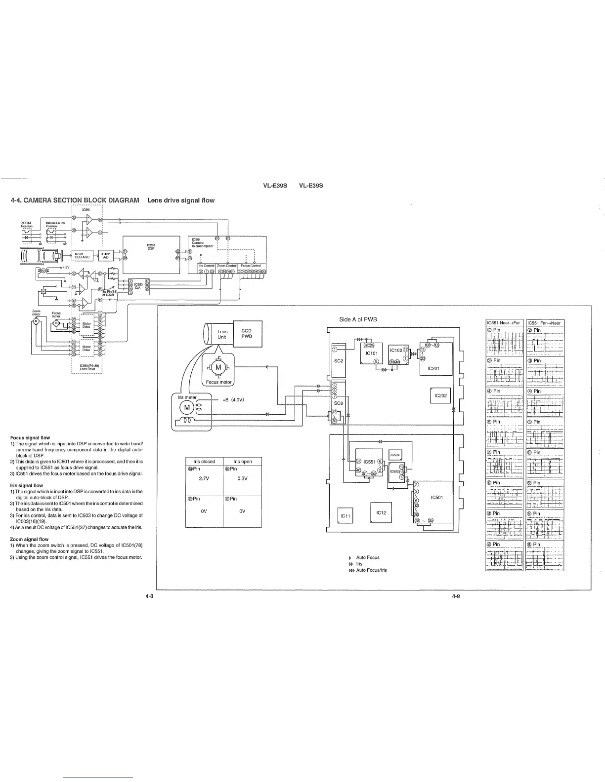
CAMERA SECTION BLOCK DIAGRAM Lens
drive
signal
flow
(J) Pin
® Pin
@)
Pin
(@
Pin
wt~1
@Pin
® Pin
'~
@)
Pin
___
!~!
a _
--------
---
@Pin
® Pin
___
1.--•• • • _
IC551
Near-tFar
IC551
Far-tNear
(2) Pin
"!
'
rr
I
II
I
rl
:=:F~;\_bl
··'T··rr.l-Fl
.:i-j4if-I-W
i/
iI
1·1
~
~-lL
-I
t;
:h
f--------j
(J) Pin
------'--i
.-~·:~W:4tl-~~:
~LL
__
L:
_.~
~
Auto Focus
» Iris
»~
Auto Focus/Iris
Side A of PWB
CCD
PWB
+B (4.9V)
Lens
Unit
Focus motor
IC501
Camera :
microcomputer:
I
1-----
7
-------------
- - -
0-
- - - - - - - - - - - - -
~
- - - - - - -
--.
, "
, "
I : I
Iris closed
Iris open
@Pin
@Pin
2.7V O.3V
(j])Pin (j])Pin
OV
OV
IC201
DSP
IC551(P9-39)
LensDrive
Focus
I , ,
motor I I
[
~
:
M
O
l
or
;
I I Drive I
, ,
1,
'
:
I.
J
'-----<;,.{J:16
1
I
~
- - - - - - -
--
- - - -
--.
j IC551 j
,
Masler-Le ns
Position
'------+fJ19
~
~
~
4
'
9
V
'
,
~IO
~:3
- -
40[1-<'
)-i-'~
=~!
;'
..
~"
""''''
:
:011C501
,
44!)--+---'I""-----------------If-----/
M
Zoom
motor
Focus
signal flow
1) The signal which is input into DSP si converted to wide band/
narrow band frequency component data in the digital auto-
block of DSP.
2) This data is given to IC501 where it is processed, and then it is
supplied to IC551 as focus drive signal.
3) IC551 drives the focus motor based on the focus drive signal.
Iris signal flow
1)The signal which is input into DSP is converted to iris datain the
digital auto-block of DSP.
2) The iris data is
sentlo
IC501 wherethe iris control is determined
based on the iris data.
3) For iris control, data is sent to IC503 to change DC voltage of
IC503(18)(19).
4)As a result DC voltageof IC551 (37) changesto actuatethe iris.
Zoom
signal flow
1) When the zoom switch is pressed, DC voltage of IC501 (78)
changes, giving the zoom signal to IC551.
2) Using the zoom control signal, IC551 drives the focus motor.
4-8
4-9