Do you have a question about the Sharp VL-A111S/H/E and is the answer not in the manual?
Detailed steps for removing the camera section from the main unit.
Step-by-step instructions for disassembling the VCR main body.
Procedures for safely replacing the CCD sensor.
Lists necessary jigs, tools, and parts for mechanism checks and adjustments.
Outlines periodic inspection and maintenance items and their timings.
Details checks and adjustments for various mechanism functions.
Procedures for adjusting the tape running system for optimal performance.
Explains the process of assembling mechanisms and replacing parts.
Step-by-step guide for correctly assembling the mechanism components.
Crucial notes and checks required before starting electrical circuit adjustments.
Identifies conditions that necessitate electrical circuit adjustment.
Steps for setting data in E2PROM for proper device operation.
Describes various test modes for diagnosing and verifying unit functions.
Procedure to adjust the battery shutoff voltage level.
Specific calibration and adjustment procedures for the VCR section.
Specific calibration and adjustment procedures for the camera section.
Illustrates the overall system architecture and component interconnections.
Details the flow of signals through the device's processing units.
Provides an overview of the device's power distribution system.
Diagram of the main battery charging and control circuit.
Block diagram illustrating the lens drive system's components and signals.
Comprehensive schematic detailing the entire device's circuitry.
Schematic for the Analog-to-Digital converter section.
Schematic detailing the zoom function for specific models.
Schematic for the Digital Signal Processor for specific models.
Schematic for the Digital Signal Processor for specific models.
Schematic of the audio processing circuits.
Schematic for the system control unit for specific models.
Schematic for the system control unit for specific models.
Schematic of the interface between LCD and main unit.
Schematic of the power control circuitry.
Schematic for the video output stage.
Schematic for the Digital-to-Analog converter section.
Schematic for the battery charging circuit.
Schematic for the LCD controller.
Schematic for the RF section for specific models.
Schematic for the RF section for specific models.
Schematic for the Timing Generator circuit.
Schematic for the CDS AGC/ACC circuits.
Schematic for the lens driver circuitry.
Schematic for the head amplifier circuit.
Schematic for the motor driver circuits.
Schematic for the CCD sensor circuitry.
Component layout for the VCR PWB, component side.
Wiring layout for the VCR PWB, wiring side.
Component layout for the Camera PWB, component side.
Wiring layout for the Camera PWB, wiring side.
Component layout for the Head Amp PWB, component side.
Wiring layout for the Head Amp PWB, wiring side.
List of electrical components for replacement, noting safety-related parts.
Lists PWBs, indicating they are not replaceable items.
Parts list for tuner and various assembly units.
List of integrated circuits with part numbers and descriptions.
List of transistors with part numbers and descriptions.
List of diodes with part numbers and descriptions.
List of packaged circuits and their part numbers.
List of coils and transformers with part numbers.
List of capacitors with part numbers.
List of resistors with part numbers.
List of baluns with part numbers.
List of various other parts not categorized elsewhere.
Specific parts list for the camera unit.
Lists mechanism parts included in the set's packing.
Lists cabinet parts included in the set's packing.
Lists accessories provided with the set.
Lists packing materials not intended for replacement.
Exploded view illustrating the assembly of the mechanism chassis.
Exploded view showing the assembly of the device's cabinet.
Exploded view illustrating the assembly of the camera unit.
| Camcorder type | Analog |
|---|---|
| Focus | Auto/Manual |
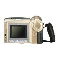
| Viewfinder | Color LCD |
| Image Sensor | CCD |
| LCD screen size | 2.5 inches |
| Recording Media | VHS-C |
| Weight | 750 grams |