5
VL-A111S/H/E/AH131S/H/E
VL-AH151S/H/E
3-2. DISASSEMBLY OF THE VCR MAIN BODY
(1) Slide the “VCR lid knob” in the arrow direction, and slide the
VCR lid in the arrow direction as far as the cabinet L fastening
screw is visible. (Left figure) Since the connector of the
microphone is still connected, take care to prevent exces-
sively sliding the VCR lid.
<2. Disassembly of the cabinet L>
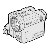
(3) Pull out the VCR lid shaft head which projects beyond the
surface of the VCR lid.
<Detail of area A>
(2) Bring the jig (example: slotted precision screwdriver) into
contact with the removal groove of the VCR lid shaft, and
slide the screwdriver with care to prevent damaging the VCR
lid and frame V.
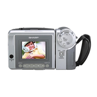
(1) Remove one screw ((k)LX-HZ0063TAFN).
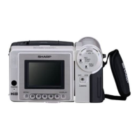
(2) Remove five screws ((b)LX-HZ0018TAFF).
(3) Turn the tilt frame C so that the screwdriver can be easily
inserted, and remove two screws ((i)XiPSN20P04000).
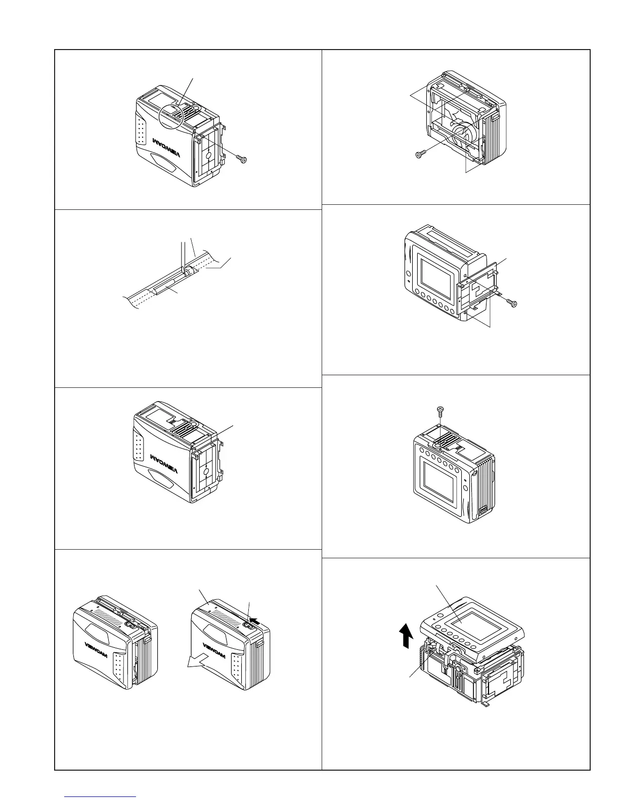
(4) Remove one screw ((i)XiPSN20P04000).
(b)
(i)
(i)
(k)
(5) Remove the cabinet L partway, and disconnect the FPC
connector.
<1. Removal of the VCR lid shaft>
VCR lid shaft
Area A
VCR lid
Frame V
VCR lid shaft
VCR lid
VCR lid knob
Tilt frame C
FPC connector
Cabinet L