24
VL-A111S/H/E/AH131S/H/E
VL-AH151S/H/E
1
6
5
2
7
4
8
3
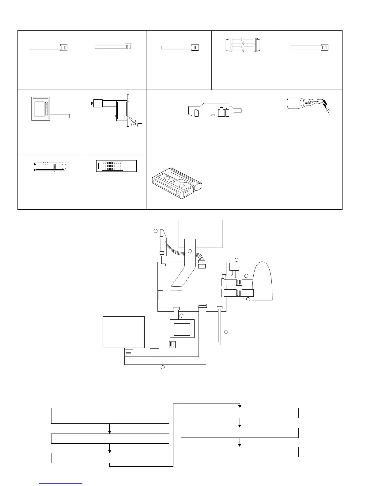
AV OUT
DC-IN
AV JACK
UNIT
MECHA UNIT
VCR UNIT
INVERTER
LCD UNIT
CAMERA
UNIT
<Extension Cable etc.>
1. Extension Cable LCD~
VCR (24pin)
2. QCNW-1382TAZZ
3. BD
1. Extension Cable
Inverter~VCR (7pin
)
2. QCNW-1265TAZZ
3. AX
1. Extension Cable
Camera~VCR (20pin)
2. QCNW-1774TAZZ
3. BH
1. Extension Cable
Camera~VCR (24pin)
2. QCNW-1382TAZZ
3. BD
1. Extension Cable
MECHA~VCR (70pin)
2. QCNW-1534TAZZ
3. BS
12345
6
7
8
1. Service remote control
2. RRMCG0033TASA
3. BT
· Alignment Tape
JiGWR5-5CSP (PAL) ....... Normal 8 TAPE (MONO)
JiGWR5-8CSE (PAL) ......Hi8 TAPE (MONO)
* Y/C Audio Alignment
insulating sleeve
1. Connector fitting and
withdrawing tweezers
2. 9EQPiNSET06GE
3. BR
1. Battery Terminal Unit
2. QTANZ0146TAZZ
3. AK
1. Operation Unit
2. QSW-Z0287TAZZ or
RUNTKA010WJZZ
3. AW/AS
1. AV Jack Unit
2.
RUNTK0355TAN1(A111S/H/AH131S/H/AH151S/H)
RUNTK0355TAZZ(A111E/AH131E/AH151E)
3. AS
1. Connector fitting and
withdrawing extractor
5-6-2. Procedure for VCR section adjustments
As the following explains all the procedures required for one series of adjustment for a VCR section, some of the items below are not
necessary depending on the contents of its repair or adjustment.
E
2
PROM setting in 5-3-2.
Adjustment of battery shutoff voltage in 6-5.
Supply voltage adjustment/check
Head Switching Point adjustment
Recording current adjustment
AUDIO circuit adjustment
LCD circuit /panel adjustment
Configuration
1. Name 2. Part No. 3. Code
4. Note *Model, Uses Remarks