EasyManua.ls Logo

Sharp VL-A10U

Sharp VL-A10U
97 pages
To Next Page IconTo Next Page
Loading...
VL-E990E
1
VL-A10U/UC/UA/UW/T/K
VL-AH30U/UC/T
Page
1. IMPORTANT SERVICE NOTES ......................................................................................................... 2
2. SPECIFICATIONS .............................................................................................................................. 5
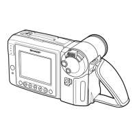
3. PART NAMES AND FUNCTION ......................................................................................................... 6
4. DISASSEMBLY OF THE SET ............................................................................................................. 7
5. MECHANISM ADJUSTMENT ........................................................................................................... 13
6. ADJUSTMENT OF VCR AND CAMERA ........................................................................................... 25
7. SYSTEM BLOCK DIAGRAMS .......................................................................................................... 38
8. SCHEMATIC DIAGRAMS ................................................................................................................. 44
9. SEMICONDUCTOR LEAD IDENTIFICATION .................................................................................. 82
10.PRINTED WIRING BOARD ASSEMBLIES ....................................................................................... 84
11.REPLACEMENT PARTS LIST .......................................................................................................... 95
12.PACKING OF THE SET .................................................................................................................. 113
S10U5VL-AH30U
SERVICE MANUAL
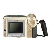
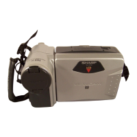
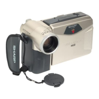
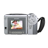
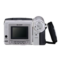
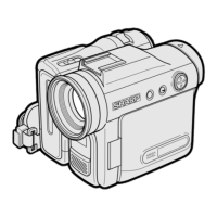
LIQUID CRYSTAL CAMCORDER Hi 8 NTSC
CONTENTS
SERVICE MANUAL
This document has been published to be used for
after sales service only.
The contents are subject to change without notice.
SHARP CORPORATION
LIQUID CRYSTAL CAMCORDER
Hi
NTSC
8
In the interests of user-safety (Required by safety regula-
tions in some countries) the set should be restored to its
original condition and only parts identical to those specified
be used.
MODELS
MODELS VL-A10U/UC/UA/UW/T/K/AH30U/UC/T
VL-A10U/UC/UA/UW
VL-A10T/K
VL-AH30U/UC/T
VL-A10U/UC/UA/UW/T/K
VL-AH30U/UC/T

Questions and Answers:

Sharp VL-A10U Specifications

General IconGeneral
BrandSharp
ModelVL-A10U
CategoryCamcorder
LanguageEnglish

Summary

1. IMPORTANT SERVICE NOTES

Safety Checks Before User Return

Perform essential safety checks before returning the video camera to the user.

Safety Warnings and Precautions

Electrical Shock and Fire Hazard Warnings

Warnings regarding electric shock, fire hazards, and proper handling of electrical components.

Product Specifications

3. PART NAMES AND FUNCTION

Component Identification Overview

Visual identification of camcorder parts from front, rear, and bottom views.

4. DISASSEMBLY OF THE SET

Camera Section Disassembly Procedure

Step-by-step instructions for disassembling the camcorder's camera section.

VCR Main Body Disassembly Procedure

Detailed steps for disassembling the VCR main body of the camcorder.

VCR Lid and AV Unit Removal

Procedures for removing the VCR lid, AV unit, and AV unit cover.

LCD Holder Disassembly Steps

Steps to disassemble the LCD holder assembly.

Internal VCR Component Removal

Steps for removing tilt unit, speaker, PWB, frame, and cassette compartment lid.

LCD Panel Disassembly Procedure

Detailed steps for disassembling the LCD panel assembly.

4-3. REPLACEMENT OF CCD SENSOR

CCD Sensor Handling and Precautions

Precautions and preparation steps before replacing the CCD sensor.

CCD Sensor Removal and Mounting

Steps for removing and mounting the CCD sensor.

5. MECHANISM ADJUSTMENT

Mechanism Adjustment Jigs, Tools, and Parts

Lists jigs, tools, and parts required for mechanism checks and maintenance.

Mechanism Inspection and Maintenance Schedule

Schedule and points for periodic inspection and maintenance of the mechanism.

Maintenance Notes and Cautions

Important notes and cautions regarding maintenance procedures and parts.

Mechanism Checks and Adjustments Overview

Detailed procedures for checking and adjusting various mechanism functions.

Reel Disk Height and Torque Adjustments

Procedures to check/adjust reel disk height, take-up torque, and back tension torque.

Tension Pole and Rewind Torque Adjustments

Procedures to adjust tension pole position and rewind torque.

Tape Travel System Adjustment Preparation and Procedures

Preparation and adjustment steps for the mechanism's tape travel system.

Tu Guide, Waveform, and Switching Point Adjustments

Adjusting Tu guide, checking waveforms, and post-adjustment checks.

5-5. MECHANISM ASSEMBLING AND PARTS REPLACEMENT

Mechanism Operating Modes and Cassette Control

Explanation of mechanism modes and cassette control assembly procedures.

Drum Assembly and Related Parts Disassembly

Disassembly procedures for the drum base, motor stator, and cassette control.

Drum Assembly Installation and Phase Matching

Installation of drum assembly, phase matching, and general assembling methods.

Mechanism Assembly: Loading Block and Guide Rails

Detailed steps for assembling mechanism components like loading block and guide rails.

Final Mechanism Assembly Steps

Final steps for assembling mechanism parts including drum, slide chassis, and levers.

6. ADJUSTMENT OF VCR AND CAMERA

Initial E2 PROM IC Settings Procedures

Procedure for initial setting and data alteration of the E2PROM IC.

VCR Section Circuit Adjustments Overview

Adjustments for Y/C, audio, LCD, VCR, and VCR circuit adjustments.

VCR Section Servicing Connections and Setup

Typical connections and required instruments for VCR section servicing.

VCR Section Adjustment Mode Setup

Procedure for setting up the VCR section adjustment mode and navigating options.

Battery Shut-off Voltage Adjustment Method

Method for adjusting the battery shut-off voltage.

VCR Circuit Adjustments: Power Circuit

Procedure for adjusting the camcorder's power circuit.

System Controller, Servo, and YC Circuit Adjustments

Adjustments for system controller, servo circuit, and Y/C circuit.

Audio Circuit and LCD Display Adjustments

Adjusting audio filter, checking audio, and adjusting LCD display circuits.

LCD Display and Bias Adjustments

Adjusting VCO, H-position, Pulse, Bias, and White Balance for LCD.

Camera Section Servicing Requirements

Required tools, jigs, and connections for camera section servicing.

Camera Adjustment Procedures Overview

Step-by-step procedures for adjusting the camera section.

Camera Signal and Auto Focus Adjustments

Adjusting power supply, auto focus, and camera signal parameters.

Camera White Balance and Gain Adjustments

Adjusting white balance, color gain, and outdoor white balance.

6-5. TROUBLE SHOOTING

General Troubleshooting Classification

Categorizes common troubles and suggests circuits to check.

Camera and Charging Mode Troubleshooting

Troubleshooting steps for camera issues and charging mode problems.

7. SYSTEM BLOCK DIAGRAMS

Overall System Block Diagram

High-level block diagram of the camcorder's system.

Signal Path Block Diagrams

Block diagrams for video signal, head amp, power, battery, and lens drive.

8. SCHEMATIC DIAGRAMS

Overall Schematic Diagram

Comprehensive schematic diagram of the camcorder's overall circuitry.

Specific Circuit Schematics

Schematics for various circuits including ADC, DSP, Audio, Power, RF, Lens, Motor Driver, CCD, and more.

9. SEMICONDUCTOR LEAD IDENTIFICATION

Semiconductor Lead Identification Guide

Identification of various semiconductor parts and their lead configurations.

Semiconductor Lead Identification Details

Continued identification of semiconductor leads and part numbers.

10. PRINTED WIRING BOARD ASSEMBLIES

VCR PWB Layout Diagrams

Layout diagrams for the VCR Printed Wiring Board (Component and Wiring Sides).

VCR PWB Wiring Side Layout

Wiring layout diagrams for the VCR Printed Wiring Board (Side A).

Camera PWB Layout Diagrams

Layout diagrams for the Camera Printed Wiring Board (Component and Wiring Sides).

Head Amp PWB Layout Diagrams

Layout diagrams for the Head Amp Printed Wiring Board (Component and Wiring Sides).

11. REPLACEMENT PARTS LIST

Electrical Parts List: ICs and Transistors

List of replacement electrical parts including integrated circuits and transistors.

Electrical Parts List: Diodes, Coils, and Capacitors

List of replacement electrical parts: diodes, coils, and capacitors.

Capacitor and Resistor Parts Lists

Detailed list of replacement capacitors and resistors.

Capacitor and Resistor Parts Lists (Continued)

Continued detailed list of replacement capacitors and resistors.

Resistor Parts List (Continued)

Continued detailed list of replacement resistors.

Resistor Parts List (Continued)

Continued detailed list of replacement resistors.

Resistors, Semiconductors, and Integrated Circuits

Lists resistors, semiconductor components, and integrated circuits for replacement.

Transistors, Transformers, Capacitors, and Resistors

Lists replacement transistors, transformers, capacitors, and resistors.

Capacitors, Resistors, and Miscellaneous Parts

Lists replacement capacitors, resistors, and miscellaneous parts.

Resistor and Miscellaneous Parts Lists

Lists replacement resistors and miscellaneous parts.

Capacitors, Miscellaneous, and Transistor Parts

Lists replacement capacitors, miscellaneous parts, and transistors.

MECHANISM PARTS

List of replacement parts for the camcorder's mechanism.

CAMERA UNIT PARTS

List of replacement parts for the camera unit.

VCR Unit Parts List

List of replacement parts for the VCR unit.

Cassette Housing and Camera Unit Parts

Lists replacement parts for cassette housing and camera unit.

PACKING PARTS (NON-REPLACEMENT)

Packing Materials List

List of packing materials such as cases, bags, and wrapping paper.

Exploded Views

Chassis and Cabinet Exploded Views

Exploded views of the mechanism chassis and the camcorder cabinet.

Sub-Assembly Exploded Views

Exploded views of cassette housing control unit and camera unit.

12. PACKING OF THE SET

Set Packing Instructions

Instructions for packing the camcorder set and its accessories for shipment.

Related product manuals