34
VL-A10U/UC/UA/UW/T/K
VL-AH30U/UC/T
6-4-2-1. Checking the power supply voltage
• Measuring terminal:
P-CON 4.9V
P-CON 3.1V
CAM 15V
CAM -8V
LENS 5.7V
• Measuring instrument: Digital voltmeter
6-4-2-3. Adjustment of Camera signal
• Before starting these adjustment, auto focus adjustment must be finished.
• Set up the camera signal adjustment mode (Write 00 to the address 70)
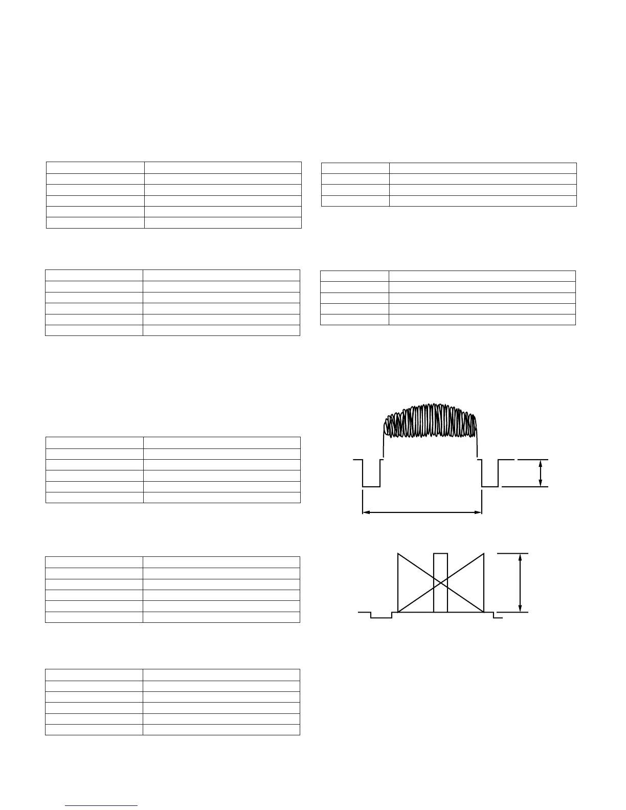
1. Sync level adjustment
Measuring instrument Oscilloscope
Subject Anything
Tape —
Test point VIDEO OUT (Terminated in 75Ω)
Adjustment address 74
Adjustment level 286mVp-p
1) Connect the oscilloscope to the VIDEO-OUT. Adjust the sync
level to 286mVp-p.
1H
Video
SYNC
286mVp-p
6-4-2-2. Auto focus adjustment
Measuring instrument None
Subject —
Tape —
Test point None
Adjustment address 71
Adjustment level 09, 0A, 0B
• Basic iris adjustment
1) Set up the auto focus adjustment mode. (Write 01 to the address 70)
2) Write the adjustment data 09, 0A and 0B one after the other to the address 71, the adjustment are as above.
DATA Adjustment
09 Hall offset
0A Iris offset
0B Iris close
• Lens adjustment
Measuring instrument None
Subject More than 50 m away
Tape —
Test point None
Adjustment address 71
Adjustment level 12, 06, 08, 0D
DATA Adjustment
12 Optical wide-end adjustment
06 Wide-end focus ∞ position adjustment
08 Tele-end focus ∞ position adjustment
0D Zoom tracking adjustment
1) Set up the auto focus adjustment mode.
(This is unnecessary after the above basic iris adjustment has been made.)
2) Write the adjustment data 12, 06, 08 and 0D one after the other to the address 71. The adjustments are as above.
Write FF to the address 70 to exit the auto focus adjustment mode.
700mVp-p
Measuring instrument Oscilloscope
Subject Gray scale
Tape —
Test point VIDEO-OUT
Adjustment address 9C
Adjustment level 700mVp-p
1) Shoot the gray scale in the standard way. Observe the VIDEO-OUT signal on the oscilloscope screen and rewrite the data of
address 9C to get an amplitude of 700mVp-p as shown above.
2. Iris AE adjustment
3. Black balance , AF noise level adjustment
Measuring instrument None
Subject Anything
Tape —
Test point None
Adjustment address 71
Adjustment level 01
1) Write the data 01 to the address 71.
The following adjustments are automatically
carried on ; 1 Black balance adjustment
2 AF noise level adjustment
at AGC Gain Min , AGC Gain Max and Gain up.