EasyManua.ls Logo

Sharp VL-AD260U User Manual

Sharp VL-AD260U
97 pages
To Next Page IconTo Next Page
Page #1 background imageLoading...
Page #1 background image
1
VL-AD260U
Page
1. IMPORTANT SERVICE NOTES......................................................................................................... 2
2. SPECIFICATIONS .............................................................................................................................. 5
3. PART NAMES AND FUNCTION ........................................................................................................ 6
4. DISASSEMBLY OF THE SET ............................................................................................................ 7
5. MECHANISM ADJUSTMENT ........................................................................................................... 13
6. ADJUSTMENT OF VCR AND CAMERA .......................................................................................... 24
7. SYSTEM BLOCK DIAGRAMS .......................................................................................................... 37
8. SCHEMATIC DIAGRAMS................................................................................................................. 46
9. PRINTED WIRING BOARD ASSEMBLIES ...................................................................................... 84
10.REPLACEMENT PARTS LIST ......................................................................................................... 97
11.PACKING OF THE SET.................................................................................................................. 114
S51T2VL-AD260
SERVICE MANUAL
LIQUID CRYSTAL CAMCORDER Hi 8 NTSC
CONTENTS
This document has been published to be used for
after sales service only.
The contents are subject to change without notice.
SHARP CORPORATION
In the interests of user-safety (Required by safety regula-
tions in some countries) the set should be restored to its
original condition and only parts identical to those specified
be used.
MODEL
SERVICE MANUAL
LIQUID CRYSTAL CAMCORDER
Hi
NTSC
8
MODEL VL-AD260U
VL-AD260U
Question and Answer IconNeed help?

Do you have a question about the Sharp VL-AD260U and is the answer not in the manual?

Sharp VL-AD260U Specifications

General IconGeneral
BrandSharp
ModelVL-AD260U
CategoryCamcorder
LanguageEnglish

Summary

1. IMPORTANT SERVICE NOTES

2. SPECIFICATIONS

AC Adapter and SmartMedia Card Specifications

Technical details for the AC adapter and SmartMedia card.

Service Information and Website

Contact details and online resources for customer support.

3. PART NAMES AND FUNCTION

Device Views (Front, Rear, Bottom)

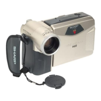
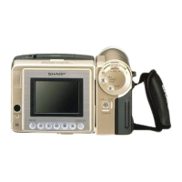
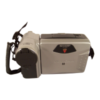
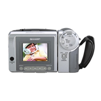
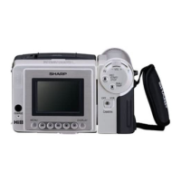
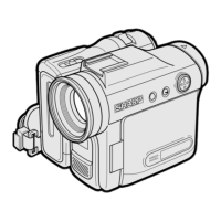
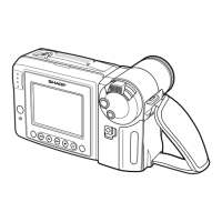
Identification of controls and features on different device views.

4. DISASSEMBLY OF THE SET

4-1. REMOVAL OF THE CAMERA SECTION

Procedures for safely dismantling the camera module.

4-2. DISASSEMBLY OF THE VCR MAIN BODY

Procedures for safely dismantling the VCR unit.

4-3. REPLACEMENT OF CCD SENSOR

Detailed steps for replacing the CCD image sensor.

5. MECHANISM ADJUSTMENT

Jigs, Tools, and Parts for Mechanism Adjustment

Listing of specialized tools and parts required for mechanism tuning.

Inspection and Maintenance Schedule and Notes

Periodic inspection tasks, timings, and important cautions.

Mechanism Checks and Adjustments

Detailed procedures for checking and adjusting various mechanism functions.

Tape Travel System Adjustment Procedures

Steps for aligning and adjusting the tape path for optimal performance.

Mechanism Assembly and Disassembly Procedures

Guidelines for taking apart and reassembling mechanism components.

Mechanism Assembly Steps

Step-by-step instructions for reassembling the device mechanism.

6. ADJUSTMENT OF VCR AND CAMERA

E²PROM IC Initial Settings and Procedures

Initial data configuration for the E²PROM IC after replacement.

Y/C, Audio, and LCD Circuit Adjustments

Procedures for tuning video, audio, and LCD display circuits.

VCR Section Adjustments

Detailed adjustment steps for the VCR circuitry.

Camera Section Adjustments

Procedures for adjusting camera functions like focus, white balance, and color.

Troubleshooting Guide for Common Issues

Systematic approach to diagnosing and resolving operational problems.

7. SYSTEM BLOCK DIAGRAMS

Power System Block Diagram

Overview of the device's power distribution system.

Battery Circuit Block Diagram

Diagram illustrating the battery charging and management system.

Lens Drive Block Diagram

Schematic showing the control flow for the lens drive system.

Signal Flow Block Diagrams

Diagrams illustrating signal paths for video and audio processing.

Card and Tape Recording/Playback Block Diagrams

Block diagrams for card and tape recording and playback operations.

8. SCHEMATIC DIAGRAMS

Overall Schematic Diagram

A comprehensive circuit diagram of the entire device.

DSP and Audio Schematics

Circuit diagrams for the Digital Signal Processor and audio systems.

System Control and LCD Schematics

Circuit diagrams for system control and LCD interface.

Power and Video Out Schematics

Circuit diagrams for power supply and video output stages.

D/A, Charge, and LCD Control Schematics

Circuit diagrams for D/A converter, charging, and LCD control.

Interface and RF Schematics

Circuit diagrams for card interface and radio frequency components.

TG, CDS, and Lens Drive Schematics

Circuit diagrams for TG, CDS, and lens drive systems.

Socket, Head Amp, and Motor Driver Schematics

Circuit diagrams for sockets, head amplifier, and motor drivers.

CCD Schematic Diagram

Circuit diagram detailing the Charge-Coupled Device sensor.

9. PRINTED WIRING BOARD ASSEMBLIES

VCR PWB Layouts (Component & Wiring Sides)

Visual guide to component placement and wiring on VCR PCBs.

Camera PWB Layouts (Component & Wiring Sides)

Visual guide to component placement and wiring on Camera PCBs.

Card PWB Layouts (Component & Wiring Sides)

Visual guide to component placement and wiring on Card PCBs.

Head Amp PWB Layouts (Component & Wiring Sides)

Visual guide to component placement and wiring on Head Amp PCBs.

10. REPLACEMENT PARTS LIST/ EXPLODED VIEWS

Electrical Parts List (ICs, Transistors, Coils, Resistors)

Comprehensive list of electrical components with part numbers.

Mechanism and Cabinet Parts Lists

Lists of mechanical and cabinet components for replacement.

Exploded Views of Major Assemblies

Visual breakdowns of mechanism, cabinet, and unit assemblies.

11. PACKING OF THE SET

Packing Components and Accessories Guide

Instructions and list for packaging the product and its accessories.

Related product manuals