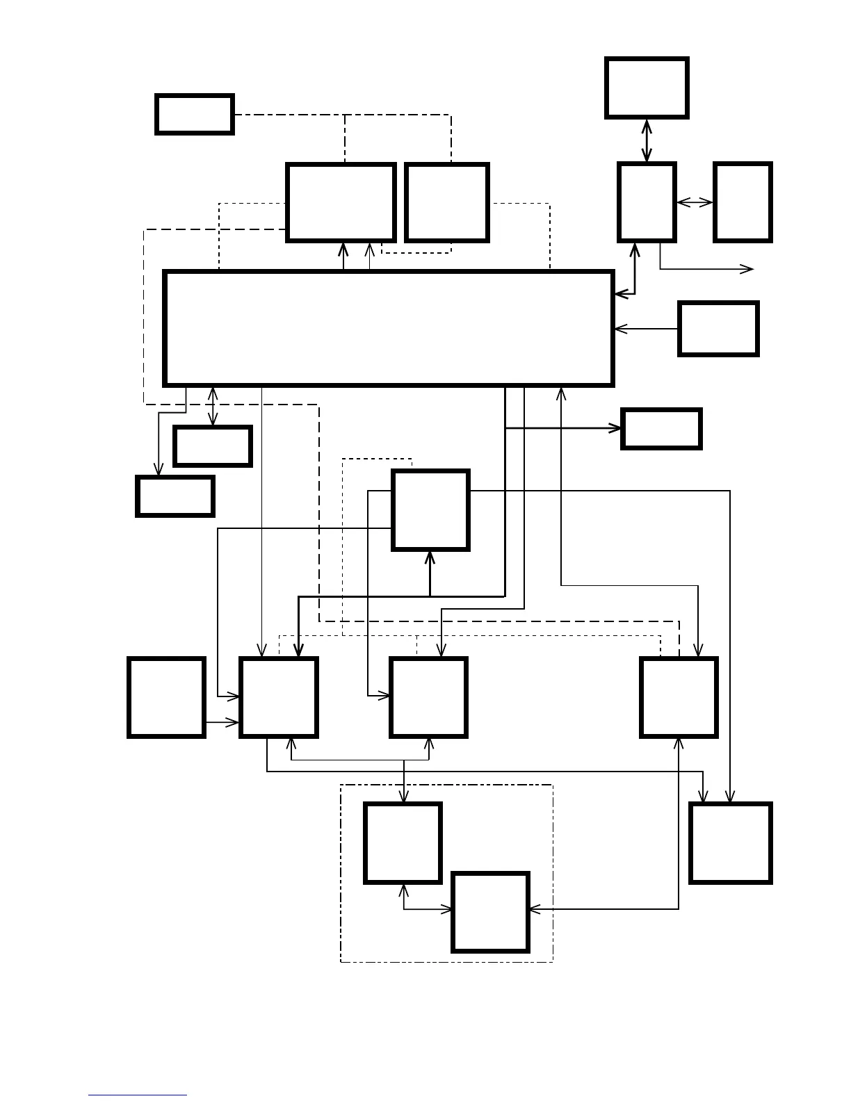
37
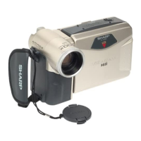
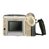
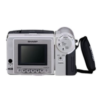
VL-AD260U
* On this model, all the circuits of the VCR and camera sections are controlled by IC706.
1) IC203 is controlled with the serial data from IC706.
2) IC705 is a memory that serves to store the adjustment data of the VCR section.
3) IC2 is a memory that serves to store the adjustment data of the camera section.
4) The other circuits and ICs are under the L/H level or the PWM control.
BATTERY
NONREGE
IC900
IC2
DSP
IC203
IC601
IC3801
IC2701
D/A
IC706
IC705
POWER (CAMERA)
E
2
PROM
LENS
E
2
PROM
SERIAL BUS
CAM
Y/C
ATF
CAM
HEAD
AUDIO
SERVO
CIRCUIT
LCD
CONTROLER
H/A
UNIT
MECHA-
NISM
MECHA-
CHASSIS
POWER (SIGNAL)
POWER (MOTOR)
SYSTEM/SERVO
CONTROL
KEY
3.0V
Reg
POWER (AT 3.0V)
POWER (SYS 3.0V)
Power Control IC
CAMERA
CONTROL
IC701
I CHIP µ-COM
CARD
MICON
IC5701
16MB
DRAM
IC5703
SmartMedia
UNIT
PC
7. SYSTEM BLOCK DIAGRAMS