EasyManua.ls Logo

Sharp VL-E630U/T User Manual

Sharp VL-E630U/T
36 pages
To Next Page IconTo Next Page
Page #1 background imageLoading...
Page #1 background image
yp&yT
VL:E665Urr
SHARP
SERVICE MANUAL
SYBASJL-E630U
LIQUID CRYSTAL CAMCORDER
q
NTSC
VL-E630U/T
VL=E680U
MODELS
VL-E685U/T
In
the
interests
of
user-safety
(Required by
safety regula-
tions in
some
countries)
the
set should be restored to its
original
condition and
only parts
identical to those specified
be used.
CONTENTS
Page
2. SPECIFICATIONS
..............................................................................................................................
2
4. DISASSEMBLY OF THE SET
.............................................................................................................
3
5. MECHANISM ADJUSTMENT..
...........................................................................................................
4
6. ADJUSTMENT OF
VCR..
....................................................................................................................
5
8. SCHEMATIC DIAGRAMS..
................................................................................................................
8
11
.REPLACEMENT PARTS LIST
..........................................................................................................
29
12.PACKlNG OF THE SET
....................................................................................................................
35
SHARP CORPORATlON
This document has been published to be used for
after sales service only.
The contents are subject to change without notice.
Question and Answer IconNeed help?

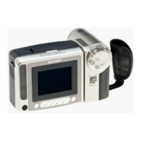
Do you have a question about the Sharp VL-E630U/T and is the answer not in the manual?

Sharp VL-E630U/T Specifications

General IconGeneral
BrandSharp
ModelVL-E630U/T
CategoryCamcorder
LanguageEnglish

Summary

2. Specifications

4. Disassembly of the Set

4-2. Disassembly of the VCR Main Body

Steps for disassembling the VCR main unit.

4-3. Replacement of CCD Sensor

Precautions and procedure for replacing the CCD sensor.

4-4. Initial Setting of EPROM IC

Settings and adjustments for the EPROM IC after replacement.

5. Mechanism Adjustment

5-2. Items and Timings of Inspection and Maintenance

Maintenance schedule and inspection points for the mechanism.

5-4. Adjustment of Mechanism Tape Travel System

Procedures for adjusting the mechanism tape travel system.

6. Adjustment of VCR

6-1. Adjustment of VCR Section

Adjustment procedures for the VCR section.

6-2. Adjustment of Camera Section

Adjustment procedures for the camera section.

8. Schematic Diagram

8-2. Power Circuit Schematic Diagram

Schematic diagram of the power circuit.

8-3. Audio Circuit Schematic Diagram

Schematic diagram of the audio circuit.

8-4. Motor Driver Schematic Diagram

Schematic diagram for motor drivers.

8-5. LCD Display Circuit Schematic Diagram

Schematic diagram of the LCD display circuit.

8-6. RF Circuit Schematic Diagram

Schematic diagram of the RF circuit.

8-7. System Control Circuit Schematic Diagram

Schematic diagram of the system control circuit.

8-9. Y/C Circuit Schematic Diagram

Schematic diagram of the Y/C circuit.

8-10. D/A Circuit Schematic Diagram

Schematic diagram of the D/A circuit.

11. Replacement Parts List / Exploded Views

Electrical Parts List

List of electrical components with part numbers and codes.

Printed Wiring Board Assemblies

List of PWB assemblies with part numbers, including those not for replacement.

Mechanism Chassis Exploded View

Exploded view diagram of the mechanism chassis with part references.

Cabinet Exploded View

Exploded view diagram of the cabinet with part references.

12. Packing of the Set

Related product manuals