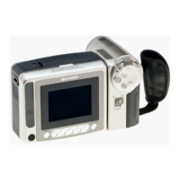
4. DISASSEMBLY OFTHE SET
4-2. Disassembly of the VCR main body
1. Removal of the VCR lid shaft
(l)Remove one screw ((j)LX-HZ0063TAFC).
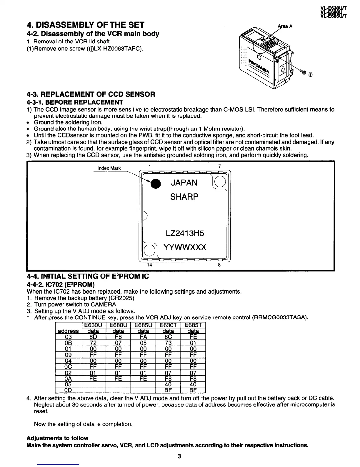
4-3. REPLACEMENT OF CCD SENSOR
4-3-l. BEFORE REPLACEMENT
1) The CCD image sensor is more sensitive to electrostatic breakage than C-MOS LSI. Therefore sufficient means to
prevent electrostatic damage must be taken when it is replaced.
l Ground the soldering iron.
l Ground also the human body, using the wrist strap(through an 1 Mohm resistor).
l Until the CCDsensor is mounted on the PWB, fit it to the conductive sponge, and short-circuit the foot lead.
2) Take utmost care so that the surface glass of CCD sensor and optical filter are not contaminated and damaged. If any
contamination is found, for example fingerprint, wipe it off with silicon paper or clean chamois skin.
3) When replacing the CCD sensor, use the antistaic grounded soldring iron, and perform quickly soldering.
Index Mark
1 7
SHARP
LZ2413H5
4-4. INITIAL SE-KING OF EzPROM IC
4-4-2. IC702 (E*PROM)
When the IC702 has been replaced, make the following settings and adjustments.
Remove the backup battery (CR2029
Turn power switch to CAMERA
Setting up the V ADJ mode as follows.
After press the CONTINUE key, press the VCR ADJ key on service remote control
1.
2.
3.
l
4.
_
After setting the above data, clear the V ADJ mode and turn off the power by pull out the battery pack or DC cable.
Neglect about 30 seconds after turned of power, because data of address becomes effective after microcomputer is
reset.
(RRMCG0033TASA).
Now the setting of data is completion.
Adjustments to follow
Make the system controller servo, VCR, and LCD adjustments according to their respective instructions.
3