VL-E39S
10-1. OPERATION
MANUAL
10-1-1.
Outline
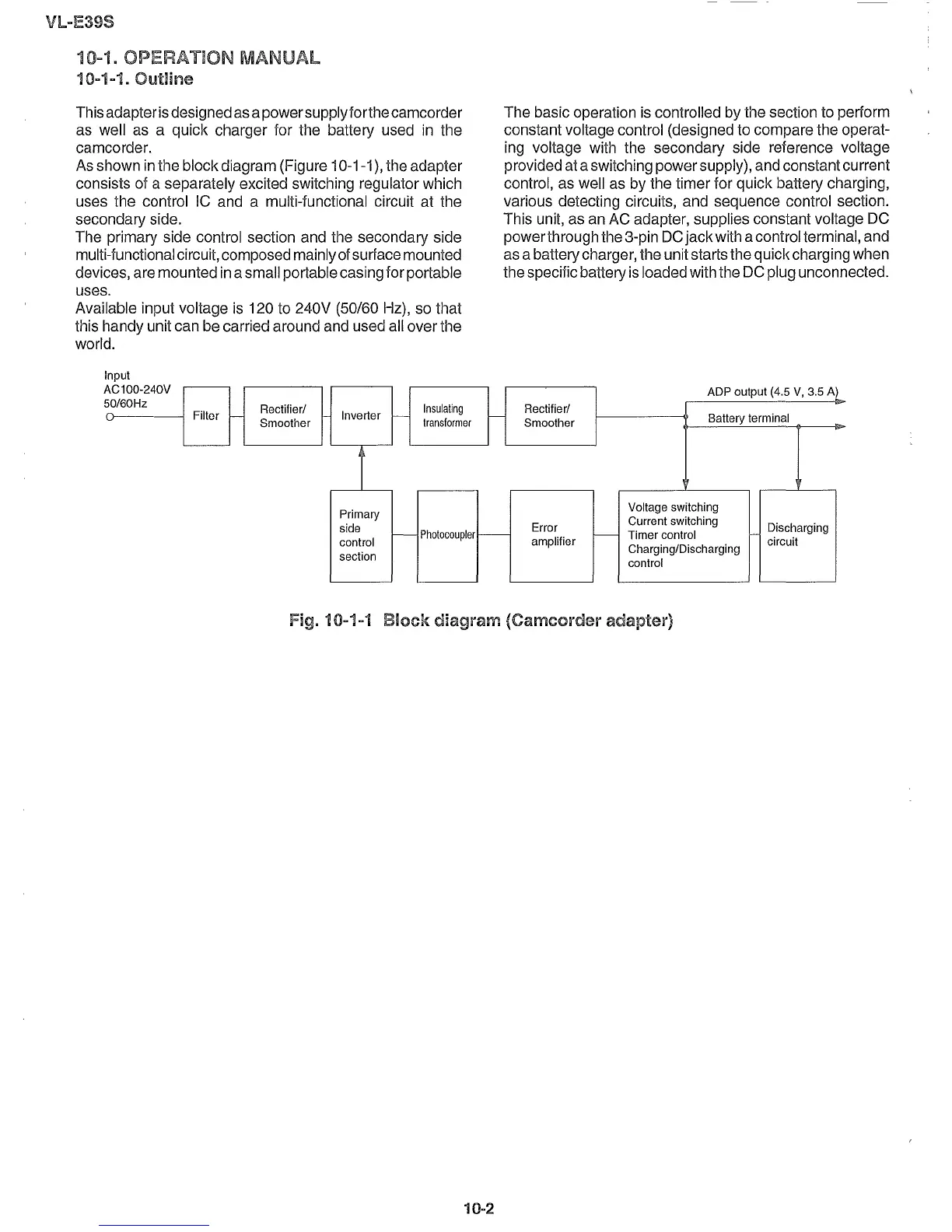
This adapter isdesignedasapower supplyforthecamcorder
as well as a quick charger for the battery used in the
camcorder.
As shown in the block diagram (Figure 10-1-1), the adapter
consists of a separately excited switching regulator which
uses the control IC and a multi-functional circuit at the
secondary side.
The primary side control section and the secondary side
multi-functional circuit, composed mainly of
surface mounted
devices, are mounted in a small portable casing for portable
uses.
Available input voltage is 120 to 240V (50/60 Hz), so that
this handy unit can be carried around and used all over the
world.
The basic operation is controlled by the section to
perform
constant voltage control (designed to compare the operat-
ing voltage with the secondary side reference voltage
provided at a switching powersupply), and constantcurrent
control, as well as by the timer for quick battery charging,
various detecting circuits, and sequence control section.
This unit, as an AC adapter, supplies constant voltage DC
powerthrough the 3-pin DC jackwith acontrol terminal, and
as a batterycharger, the unit starts the quickcharging when
the specific battery is loaded with the DC plug unconnected.
OV
ADP output (4.5
v, 3.5 A)
Filter
Rectifier/
Inverter
Insulating
Rectifier/
- -
Smoother
I---
transformer
-
Smoother
Battery terminal
Primary
Voltage switching
side
Error
Current switching
Discharging
r--
Photocoupler
-
- Timer control
control
amplifier
Charging/Discharging
circuit
section
control
Input
AC100-24
50/60Hz
0--
Fig. 10-1-1
Block
diagram
(Camcorder adapter)
10-2