5-8
VL-E610S/VL-E610H
VL-E660S/VL-E96E
VL-E98E
1. Adjustment of fixed data writing
ADD DATA
23 00
25 01
26 AB
2. Adjustment of input Y level
Measuring instrument Oscilloscope
Mode VCR STOP
Input signal Color bar
Measuring point TL801
Adjustment address 32
Adjustment level 1.0 Vp-p ± 40 mVp-p
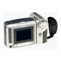
(1)Input the color bar signal into the video input/output terminal in the VCR STOP mode.
(2)Enter the VCR adjustment mode with an adjustment remote control, and select the address 32.
Select the address, using the FF or REW key, and fix it with the PB key.
(3)Make an adjustment so as to get 1.0 Vp-p between SYNC TIP and WHITE PEAK on TL801.
Select the data, using the FF or REW key, and fix it with the PB key.
After the adjustment, press the STOP key, and exit from the adjustment address 32.
3. Adjustment of playback Y level
Measuring instrument Oscilloscope
Mode PB
Playback signal Color bar (JiGWR5-5CSP)
Measuring point TL801
Adjustment address 27
Adjustment level 1.0 Vp-p ± 40 mVp-p
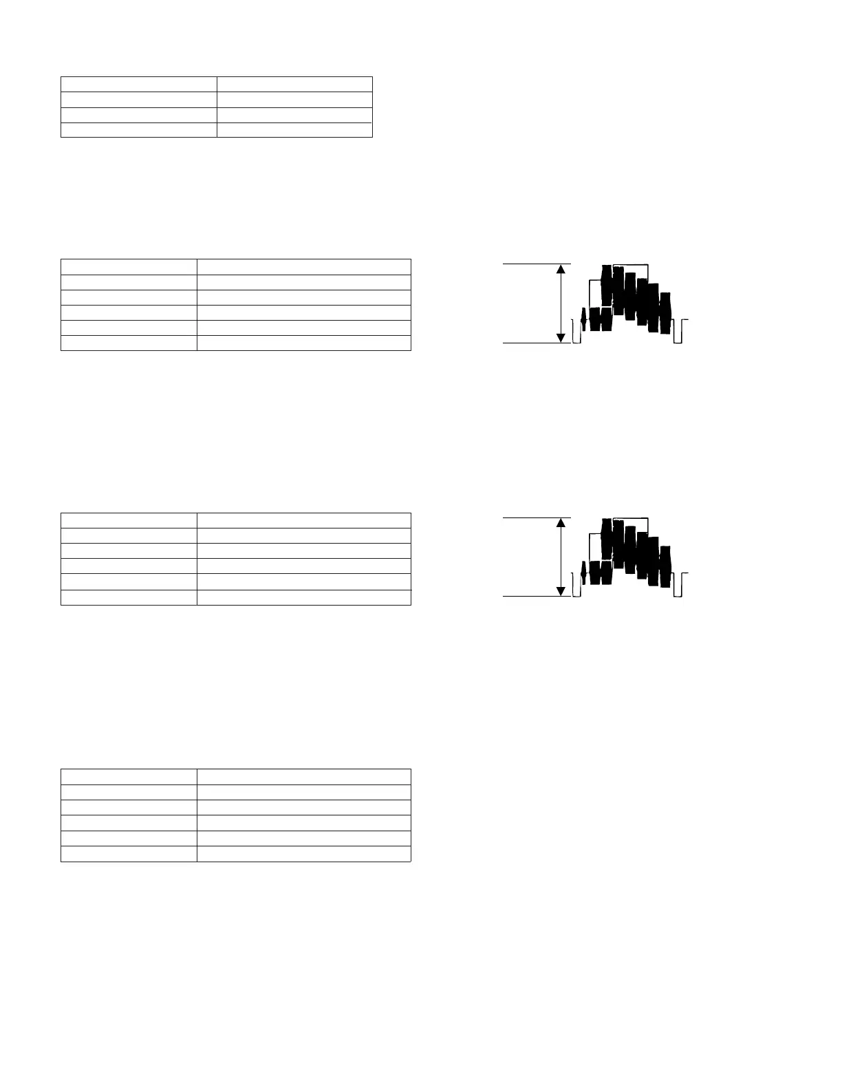
(1)Set the color bar tape for alignment (JiGWR5-5CSP).
(2)Enter the VCR adjustment mode with an adjustment remote control, and select the address 27.
Select the address, using the FF or REW key, and fix it with the PB key. (It will automatically set the playback mode.)
(3)Make an adjustment so as to get 1.0 Vp-p between SYNC TIP and WHITE PEAK on TL801.
Select the data, using the FF or REW key, and fix it with the PB key.
After the adjustment, press the STOP key, and exit from the adjustment address 27.
(1)Before starting Y/C adjustment, be sure to
write the specific data in the addresses
listed left.
If the data listed left is written after Y/C
adjustment, adjusting values may deviate.
* Before starting Y/C adjustment, write 00 to
the address 31.
* At the end of Y/C and LCD adjustment,
write FF to the address 31.
4. Adjustment of Y-FM carrier f0
Measuring instrument Frequency counter
Mode VCR STOP
Input signal No input
Measuring point TL7401
Adjustment address 33
Adjustment level 4.20 ± 0.02 MHz
(1)Input the no-signal into the video input/output terminal in the VCR STOP mode.
At this time, do not pull out the jack on the Viewcam side.
(2)Enter the VCR adjustment mode with an adjustment remote control, and select the address 33.
Select the address, using the FF or REW key, and fix it with the PB key.
(3)Make an adjustment so that the frequency counter indicates 4.2 MHz on TL7401.
Select the data, using the FF or REW key, and fix it with the PB key.
After the adjustment, press the STOP key, and exit from the adjustment address 33.
 Loading...