SHARP CORPORATION
This document has been published to be used for after
sales service only.
The contents are subject to change without notice.
In the interests of user-safety (Required by safety regulations in some countries ) the set should be restored to its
original condition and only parts identical to those specified should be used.
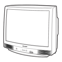
COLOR TELEVISION
Chassis No. GA-4
Page
» ELECTRICAL SPECIFICATIONS .........................................................................................................1
» IMPORTANT SERVICE SAFETY PRECAUTION .................................................................................2
» LOCATION OF USER'S CONTROL .....................................................................................................4
» INSTALLATION AND SERVICE INSTRUCTIONS ................................................................................5
» SERVICE MODE...................................................................................................................................6
» ADJUSTMENT METHOD .....................................................................................................................7
» CHASSIS LAYOUT .............................................................................................................................14
» BLOCK DIAGRAM ..............................................................................................................................15
» DESCRIPTION OF SCHEMATIC DIAGRAM......................................................................................19
» SCHEMATIC DIAGRAMS......................................................................................................................20
» PRINTED WIRING BOARD ASSEMBLIES.........................................................................................24
» REPLACEMENT PARTS LIST.............................................................................................................28
» PACKING OF THE SET ......................................................................................................................34
CONTENTS
SPEAKER
SIZE ...................................................................5 x 12 cm, 2pcs
VOICE COIL IMPEDANCE ............................ 16 ohm at 400 Hz
ANTENNA INPUT IMPEDANCE
VHF/UHF .....................................................75 ohm Unbalanced
TUNING RANGES
VHF-Channels...............................................................2 thru 13
UHF-Channels ............................................................14 thru 69
CATV Channels ...........................................................1 thru 125
(EIA, Channel Plan U.S.A.)
POWER INPUT ............................................... AC 110-220V, 60 Hz
POWER RATING .................................................................... 90W
PICTURE SIZE .......................................... 1,239 cm
2
(192sq inch)
CONVERGENCE ............................................................. Magnetic
SWEEP DEFLECTION .................................................... Magnetic
FOCUS ................................................................................. Uni-Bi
INTERMEDIATE FREQUENCIES
Picture IF Carrier Frequency ..................................... 45.75 MHz
Sound IF Carrier Frequency...................................... 41.25 MHz
Color Sub-Carrier Frequency .................................... 42.17 MHz
(Nominal)
AUDIO POWER
OUTPUT RATING ........................................4 W(RMS) x 2pcs
Specifications are subject to change without
prior notice.
ELECTRICAL SPECIFICATIONS
MODELS
SERVICE MANUAL
W21FL