WF-2100W
– 4 –
DISASSEMBLY
Caution on Disassembly
Follow the below-mentioned notes when disassembling
the unit and reassembling it, to keep it safe and ensure
excellent performance:
1. Take cassette tape out of the unit.
2. Be sure to remove the power supply plug from the wall
outlet before starting to disassemble the unit and remove
the batteries from the unit.
3. Take off nylon bands or wire holders where they need
to be removed when disassembling the unit. After
servicing the unit, be sure to rearrange the leads where
they were before disassembling.
4. Take sufficient care on static electricity of integrated
circuits and other circuits when servicing.
STEP REMOVAL PROCEDURE FIGURE
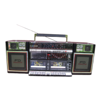
1 Front Cabinet/ 1. Screw .................. (A1) x9 4-1
Rear Cabinet 2. Socket ................. (A2) x1 4-3
3. Screw .................. (A3) x1
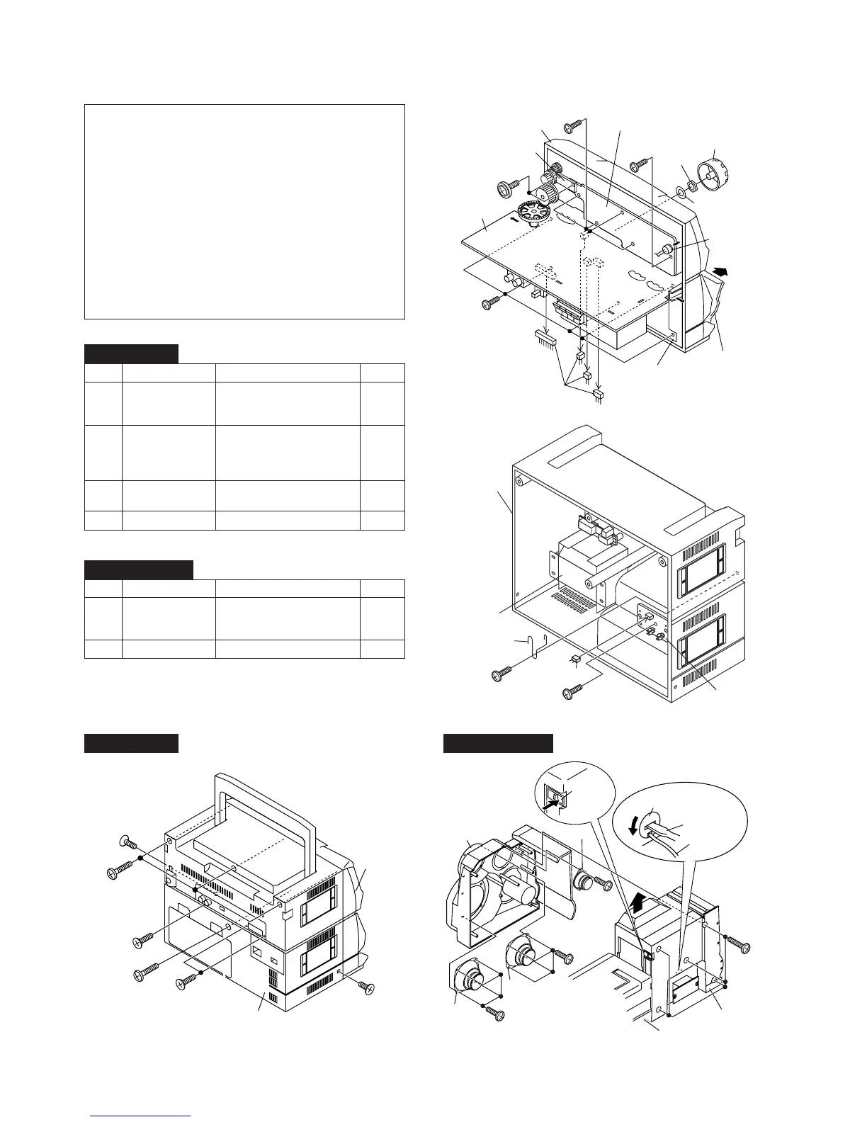
2 Main PWB/ 1. Knob.................... (B1) x1 4-2
Graphic Equalizer 2. Screw .................. (B2) x7
PWB/Fine Tuning 3. Socket ................. (B3) x4
PWB 4. Mic ...................... (B4) x1
3 Tape Mechanism 1. Open the cassette holder. 4-2
2. Screw .................. (C1) x5
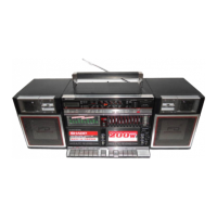
4 Power PWB 1. Screw .................. (D1) x1 4-3
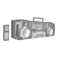
Figure 4-4
Figure 4-2
Figure 4-1
Figure 4-3
STEP REMOVAL PROCEDURE FIGURE
1 Woofer 1. Screw .................. (A1) x5 4-4
2. Front Panel ......... (A2) x1
3. Screw .................. (A3) x8
2 Tweeter 1. Screw .................. (B1) x2 4-4
MAIN UNIT
SPEAKER UNIT
Front
Cabinet
(A1)x1
ø3x8mm
Rear
Cabinet
(A1)x2
ø3x14mm
(A1)x1
ø3x8mm
(A1)x3
ø3x14mm
(A1)x1
ø3x30mm
(A1)x1
ø3x14mm
Front Cabinet
Washer
Nut
(B1)x1
(B2)x1
ø3x10mm
(B2)x4
ø3x8mm
(B2)x2
ø2.6x8mm
(C1)x5
ø3x10mm
Tape
Mechanism
(B3)x4
Cassette
Holder
Open
Graphic
Equalizer PWB
Fine Tuning PWB
(B4)x1
Main PWB