WF-2100W
– 6 –
FM IF T108 Input: FM Antenna
FM Detection T106
Output: Pin 9 of IC102
FM Band fL: L101 Input: Antenna
Coverage fH: TC1 Output: Headphones
Socket
FM Tracking fL (88.0 MHz): L102
(Load resistance: 32 ohms)
fH (108 MHz): TC2
ADJUSTMENT
Specified Value
MECHANISM SECTION
• Driving Force Check
Specified Value
• Torque Check
• Head Azimuth
MTT-114 Headphones Socket
(Load resistance: 32 ohms)
Instrument Connection
• Tape Speed (Normal only)
Instrument
Connection
MTT-111 Tape 1, Tape 2: 3,000 ± 60 Hz Headphones
VR501 Socket
(Load resistance:
32 ohms)
Torque Meter
Torque Meter
Test Tape
Test Tape
• Playback Amplifier Sensitivity Check
Play: TW-2412 Tape 1: Over 60 g
Tape 2: Over 50 g
Tape 1 Tape 2
Adjustment
Point
Specified
Value
Specified value Instrument Connection
MTT-118 2.5 V ± 3 dB Speaker terminal
(Load resistance: 8 ohms)
Test tape
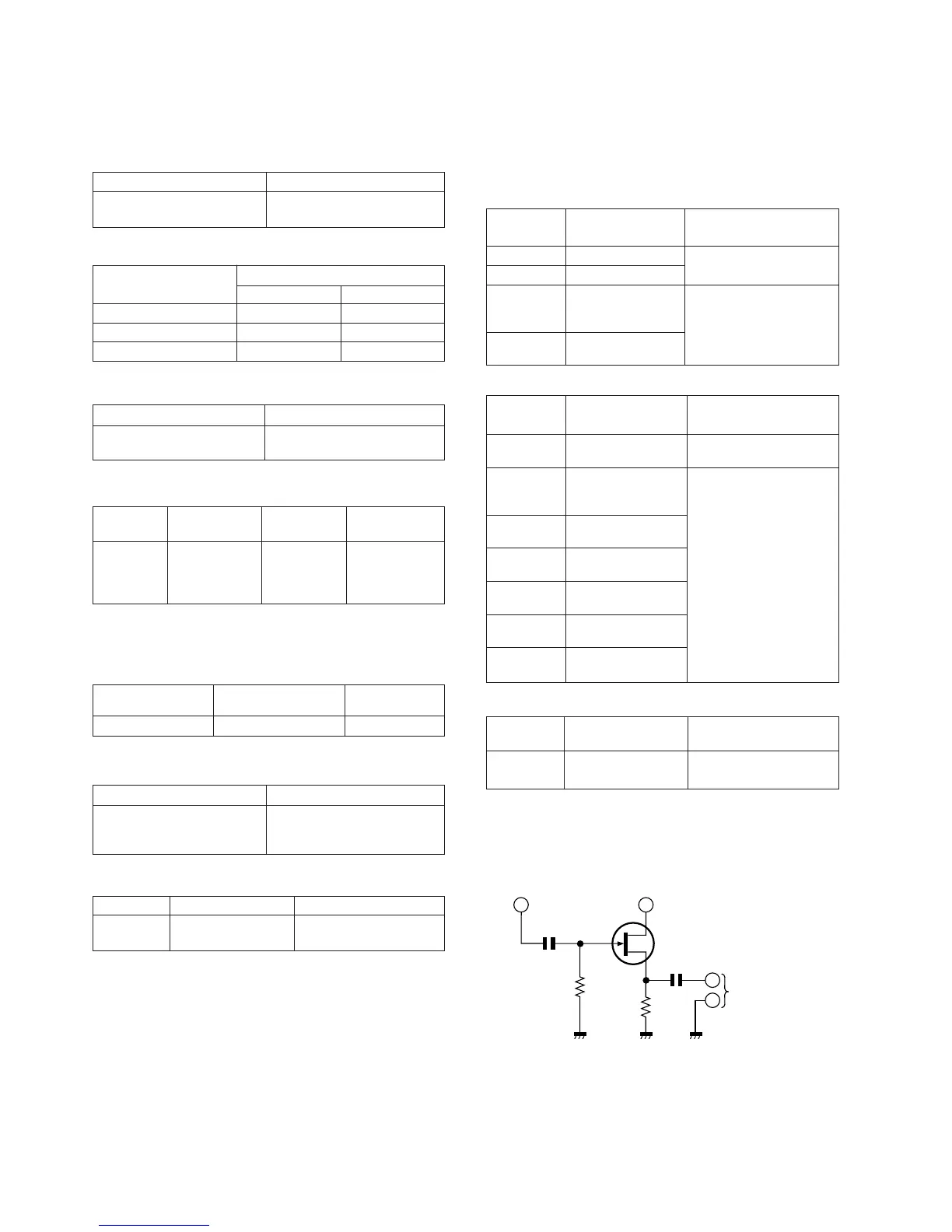
Figure 6 VCO FREQUENCY TEST CIRCUIT
TUNER SECTION
fL: Low-range frequency
fH: High-range frequency
Specified value Instrument Connection
VR102 76 kHz ± 200 Hz Pin 13, Pin 21 and ground
of IC102
Adjustment
Point
• VCO Frequency
Note:
After preparing the test circuit shown in Fig. 6, connect the Pin
13, Pin 21 and ground of the IC102 with the test circuit, and
measure the value.
Specified Value/
Adjusting Point
Test Stage
Instrument
Connection
Test Stage
Specified Value/
Adjusting Point
Instrument
Connection
AM IF T107 Input: Antenna
Output: Pin 9 of IC102
MW Band fL: T103 Input: Antenna
Coverage fH: TC3 Output: Headphones
Socket
MW Tracking fL (600 kHz): L103
(Load resistance 32 ohms)
fH (1,400 kHz): TC4
SW1 Band fL (2.3 MHz): T104
Coverage fH (7.3 MHz): CT102
SW1 fL (2.6 MHz): T101
Tracking fH (6 MHz): CT104
SW2 Band fL (7.3 MHz): T105
Coverage fH (22 MHz): CT101
SW2 fL (8.5 MHz): T102
Tracking fH (19 MHz): CT103
10 pF
1 Mohm
10 kohm
TO FREQUENCY
COUNTER
Pin 13 of IC102
Pin 21 of IC102
FET: 2SK212
(or Other 2SK Type FET.)
G
D
S
0.1 µF
Specified Value
Beat Cancel A: 100 ± 4 kHz
B: 94 ± 4 kHz
C: 104 ± 4 kHz
T201 100 kHz + 4 kHz Pin 5 of CON202
Adjustment Point Specified value Instrument
Connection
DECK SECTION
• Bias Oscillation
• FM IF/RF
Play: TW-2111 30 to 70 g.cm 27 to 60 g.cm
Fast Forward: TW-2231 Over 55 g.cm 55 to 120 g.cm
Rewind: TW-2231 Over 55 g.cm 55 to 120 g.cm
• AM IF/RF
• Beat Cancel Switch: A