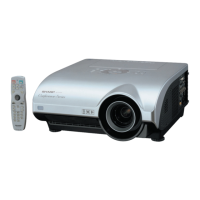
XG-P25X
29
7 Sample-and-
hold pulse
phase
RCK-PHASE
GCK-PHASE
BCK-PHASE
1. Feed the XGA mode 75-Hz
black signal.
2. Make the following choice:
Group : OUTPUT 3
Subject : SH-PHASE
(Have the standard level at
8.)
Fix the GCK-PHASE set-
tings all to 8.
» Using the control switches or the remote controller
buttons, make sure that the “OUTPUT 3” charac-
ters are not blurry and there is no ghost image. If
such blur or ghost occurs, finely adjust the setting
in the range of 7~9.
8 RGB counter-
voltage
adjustment
1. Feed the black-and-red
(25%) stripe signal (XGA).
2. Make the following choice:
Group : OUTPUT 3
Subject : RC (R)
: BC (B)
: GC (G)
» Using the control switches or the remote controller
buttons, adjust the data in order to minimize the
flicker.
» Make the same adjustment for BC (B) and GC (G).
» See if the image is equally adjusted at the center
and both sides of the screen. If not, readjust the
setting to have the image equal at right and left.
9 RGB gradation
regeneration
adjustment
1. Feed the INFO COM. gray
scale and color bar pattern.
2. Make the following choice:
Group : OUTPUT 1
Subject : G1-BLK
» Make sure that scale (white side) to No.251 and
scale (black side) to No.8 can be seen.
» If white scale can't be seen properly, readjust with
G1-BLK.
No. Adjusting point Adjusting conditions Adjusting procedure
6 P SIGNAL 1. Connect the oscilloscope to
TP1102 for red.
2. Make the following choice:
Group : OUTPUT 2
Subject : PSIG-H
: PSIG-L
» Adjust the PSIG waveform to the one shown below.
» For the green and blue colors, make sure their wave-
forms are similar to that of the red color.
2.5V DC 5.0V DC
GND
PSIG
(Adjust with PSIG-L.)(Adjust with PSIG-H.)
4812
249 251
 Loading...